Communication Protocols on STM32 (Part 8): 1-Wire and DS18B20 – time slots, CRC8 and GPIO bit-banging
1-Wire on STM32 with the DS18B20 sensor, from time slots, ROM commands, the scratchpad and CRC8 (with verified examples) to two implementations, one with GPIO and one with a UART. Part 8 of the Communication Protocols on STM32 series.
Note: the diagrams in this article were drawn by Capitlab for illustration. Table values are calculated from formulas; the "Measured" column will be filled in once measurements are made on hardware. CRC8 and the sample temperature values were checked with a program. The code was written from the HAL documentation and datasheets and has not yet been run on hardware, so verify it before using it in a product.
1-Wire was created by Dallas (later part of Maxim, now Analog Devices). It needs only one data wire plus GND and can even draw power from the data line itself (parasite power). The best-known 1-Wire device is the DS18B20 temperature sensor.
Fewer wires has a cost elsewhere: low speed and very tight timing. Being off by a few microseconds means reading the wrong bit. This part explains the time slots and how to read and verify DS18B20 data, then gives two STM32 implementations: GPIO bit-banging with a microsecond timer, and borrowing a UART so the hardware handles the timing.
1. How it works
The data line (DQ) is pulled up to the supply through a resistor, usually 4.7 kΩ. When idle the line sits high. Both master and slaves only have a transistor to pull the line to GND and release it to let it rise, so two sides never drive against each other.
Every chip has a unique 64-bit ROM code: an 8-bit family code (0x28 for the DS18B20), a 48-bit serial number and an 8-bit CRC. That is what lets one wire carry many sensors, with the master addressing each one by its ROM code.
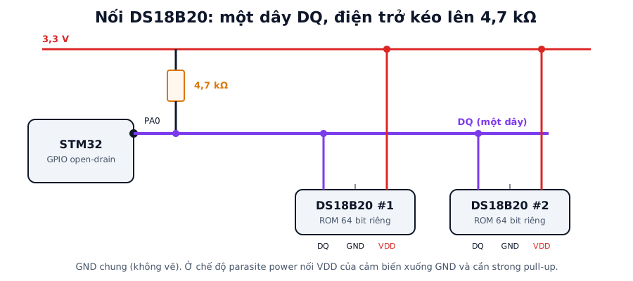
Figure 1. Two DS18B20s sharing one DQ wire with a 4.7 kΩ pull-up. The GPIO pin is configured as an open-drain output. Labels in the figure are in Vietnamese.
1.1. Time slots
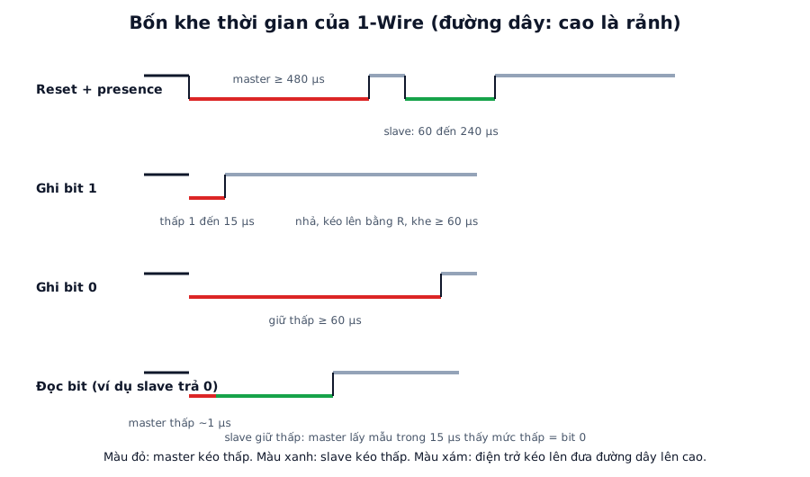
Figure 2. The four basic operations. Red is the master pulling low, green is the slave pulling low, grey is the pull-up bringing the line high.
| Operation | What the master does | Timing |
|---|---|---|
| Reset | Pull low, then release | Low for at least 480 µs |
| Presence | The slave pulls low to announce itself | 60 to 240 µs, starting about 15 to 60 µs after release |
| Write 1 | Pull low briefly, then release | Low for about 1 to 15 µs, whole slot 60 µs or more |
| Write 0 | Hold low for the whole slot | At least 60 µs |
| Read bit | Pull low for about 1 µs, release, sample within about 15 µs | Whole slot 60 µs or more |
The slave samples the line between about 15 and 60 µs after the falling edge of a write slot. Bits go out LSB first. Between slots the line needs at least 1 µs for the pull-up to bring it high again.
Reading the 9-byte scratchpad takes 72 slots. At about 70 µs per slot, the read alone takes about 5 ms, not counting the reset, ROM command and function command. That is much slower than I²C, but for a temperature sensor read a few times per second it does not matter.
1.2. Commands
Every transaction has three steps: reset, ROM command, function command.
| ROM command | Code | Meaning |
|---|---|---|
| Read ROM | 0x33 | Read the ROM code; only valid with a single slave |
| Match ROM | 0x55 | Select one slave by its 64-bit ROM code |
| Skip ROM | 0xCC | Skip addressing and talk to everyone (single slave only) |
| Search ROM | 0xF0 | Discover all devices on the bus |
| DS18B20 function command | Code | Meaning |
|---|---|---|
| Convert T | 0x44 | Start a temperature conversion |
| Read Scratchpad | 0xBE | Read the 9-byte scratchpad |
| Write Scratchpad | 0x4E | Write TH, TL and the configuration register |
The maximum conversion time depends on resolution: about 93.75 ms at 9 bits, 187.5 ms at 10 bits, 375 ms at 11 bits and 750 ms at 12 bits. If you don't need fine resolution, drop to 9 or 10 bits for faster readings.
1.3. Scratchpad and CRC8
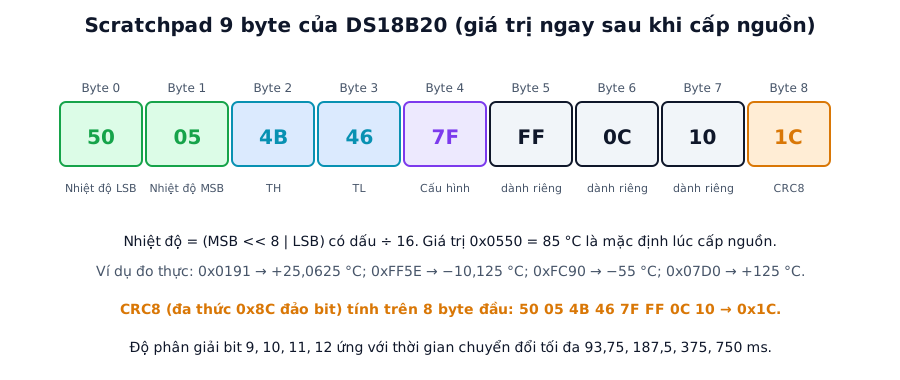
Figure 3. The 9-byte scratchpad with its values right after power-up. The default temperature 0x0550 is 85 °C.
The temperature is a signed 16-bit number divided by 16. At 12 bits each step is 0.0625 °C. Sample values from the datasheet, checked with a program:
| Raw value (hex) | Temperature |
|---|---|
| 0x07D0 | +125 °C |
| 0x0550 | +85 °C (power-up default) |
| 0x0191 | +25.0625 °C |
| 0xFF5E | −10.125 °C |
| 0xFC90 | −55 °C |
Watch out for 85 °C: it is the power-up default. Reading 85 °C usually means the conversion has not finished, or was never started.
The Dallas/Maxim CRC8 uses the polynomial x⁸ + x⁵ + x⁴ + 1 (bit-reversed 0x8C) with an initial value of 0. You can compare with the Capitlab CRC calculator using CRC-8/MAXIM:
uint8_t ow_crc8(const uint8_t *p, uint8_t n)
{
    uint8_t crc = 0;
    while (n--) {
        uint8_t b = *p++;
        for (int i = 0; i < 8; i++) {
            uint8_t mix = (crc ^ b) & 1;
            crc >>= 1;
            if (mix) crc ^= 0x8C;
            b >>= 1;
        }
    }
    return crc;
}
// Example: 50 05 4B 46 7F FF 0C 10 -> CRC = 0x1C (verified)
Running CRC8 over all 9 bytes, including the CRC byte at the end, must give 0. The same goes for the 8-byte ROM code: the CRC of the first 7 bytes equals the 8th. 1-Wire has no other error detection, so every read must be CRC-checked.
2. Method 1: GPIO bit-banging with a microsecond timer
Configure the GPIO as an open-drain output with an external pull-up. You need an accurate microsecond delay, usually a 16-bit timer running at 1 MHz:
// TIM6 runs at 1 MHz (prescaler = SYSCLK_MHz - 1), HAL_TIM_Base_Start already called
static inline void delay_us(uint16_t us)
{
    __HAL_TIM_SET_COUNTER(&htim6, 0);
    while (__HAL_TIM_GET_COUNTER(&htim6) < us) { }
}

#define OW_LOW()   HAL_GPIO_WritePin(OW_GPIO_Port, OW_Pin, GPIO_PIN_RESET)
#define OW_REL()   HAL_GPIO_WritePin(OW_GPIO_Port, OW_Pin, GPIO_PIN_SET)   // open-drain: release
#define OW_READ()  HAL_GPIO_ReadPin(OW_GPIO_Port, OW_Pin)

int ow_reset(void)
{
    OW_LOW();  delay_us(480);
    OW_REL();  delay_us(70);
    int present = (OW_READ() == GPIO_PIN_RESET);
    delay_us(410);
    return present;
}

void ow_write_bit(int b)
{
    __disable_irq();
    OW_LOW();
    delay_us(b ? 6 : 60);
    OW_REL();
    delay_us(b ? 64 : 10);
    __enable_irq();
}

int ow_read_bit(void)
{
    __disable_irq();
    OW_LOW();  delay_us(2);
    OW_REL();  delay_us(10);
    int v = (OW_READ() == GPIO_PIN_SET);
    __enable_irq();
    delay_us(50);
    return v;
}

void ow_write_byte(uint8_t v)  { for (int i = 0; i < 8; i++) { ow_write_bit(v & 1); v >>= 1; } }
uint8_t ow_read_byte(void)     { uint8_t v = 0; for (int i = 0; i < 8; i++) v |= ow_read_bit() << i; return v; }
Interrupts are disabled inside each slot because a few microseconds of drift is enough to misread a bit. Each slot in this code is about 70 µs long. The approach is simple but sensitive to system load: an RTOS and other interrupts can get in the way, and disabling interrupts, however briefly, affects other real-time tasks.
2.1. Reading one DS18B20
With a single sensor on the bus, use Skip ROM:
// Returns 0 on success, negative on error. *t is in °C.
int ds18b20_read(float *t)
{
    uint8_t sp[9];

    if (!ow_reset()) return -1;           // no sensor
    ow_write_byte(0xCC);                  // Skip ROM
    ow_write_byte(0x44);                  // Convert T
    HAL_Delay(750);                       // 12 bits (replace with a timer or RTOS so it does not block)

    if (!ow_reset()) return -2;
    ow_write_byte(0xCC);
    ow_write_byte(0xBE);                  // Read Scratchpad
    for (int i = 0; i < 9; i++) sp[i] = ow_read_byte();

    if (ow_crc8(sp, 9) != 0) return -3;   // bad CRC: discard the result

    int16_t raw = (int16_t)((sp[1] << 8) | sp[0]);
    *t = raw / 16.0f;
    return 0;
}
Reading 0x0550 (85 °C) or all 0xFF indicates a bad read, and the CRC will catch most of these. In a real product don't block the CPU for 750 ms with HAL_Delay: send Convert T, then let a timer or an RTOS task call the read later.
With several sensors, use Match ROM (0x55) followed by each sensor's 8-byte ROM code. To discover the ROM codes, use Search ROM (0xF0). The algorithm walks a binary tree bit by bit: at each bit the slaves send the bit and its complement, the master picks a branch, and the process repeats until the whole tree has been covered. Existing 1-Wire libraries already implement it.
3. Method 2: using a UART for 1-Wire
A popular trick turns each time slot into one UART byte. Connect the TX pin (configured open-drain) and the RX pin to the same 1-Wire line with its pull-up. Every byte sent is received straight back on RX, and the received byte tells you the state of the line.
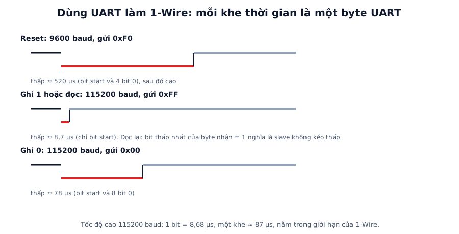
Figure 4. Each operation is one UART byte at the appropriate baud rate.
To reset, set the baud rate to 9600 and send 0xF0. The line goes low for about 520 µs (start bit plus 4 zero bits). If the byte received back differs from 0xF0, a slave was pulling the line, which means a presence pulse.
For each data bit, set the baud rate to 115200. Send 0xFF to write a 1 or to read: the start bit produces a short low pulse of about 8.7 µs. Send 0x00 to write a 0: the line stays low for about 78 µs. When reading, look at the least significant bit of the received byte: 1 means the slave did not pull low (bit 1), 0 means it did (bit 0).
// UART2 setup: TX open-drain, RX on the same 1-Wire line, 8N1
static void ow_uart_baud(uint32_t baud)
{
    huart2.Init.BaudRate = baud;
    HAL_UART_Init(&huart2);
}

static uint8_t ow_uart_slot(uint8_t out)
{
    uint8_t in = 0xFF;
    __HAL_UART_FLUSH_DRREGISTER(&huart2);          // flush stale byte (macro depends on the family)
    HAL_UART_Transmit(&huart2, &out, 1, 10);
    HAL_UART_Receive(&huart2, &in, 1, 10);         // the byte just sent echoes back on RX
    return in;
}

int ow_uart_reset(void)
{
    ow_uart_baud(9600);
    uint8_t in = ow_uart_slot(0xF0);
    ow_uart_baud(115200);
    return in != 0xF0;                             // anything other than 0xF0 means presence
}

int ow_uart_bit(int b)
{
    uint8_t in = ow_uart_slot(b ? 0xFF : 0x00);
    return (in & 0x01);                            // for reading: send b = 1
}
At 115200 baud each slot lasts about 87 µs (10 bits × 8.68 µs), within 1-Wire limits. Reading the 9-byte scratchpad takes 72 slots, about 6.25 ms, compared with about 5 ms for the GPIO method.
Here the timing comes from the UART hardware, so it does not depend on interrupts, does not require disabling them, and can be combined with DMA. In exchange it uses up a UART, and constantly changing the baud rate also takes time. On a system with many interrupts or an RTOS, the UART method is the more robust one.
4. Parasite power
The DS18B20 can draw power from the DQ line itself (with its VDD pin tied to GND) through an internal capacitor. During a conversion it needs more current than the pull-up can supply, so right after Convert T the line must be actively pulled high (strong pull-up) with a MOSFET or a push-pull GPIO and held there for the whole conversion. For a product that has to be reliable, three wires with a separate VDD is simpler.
5. Common faults
| Symptom | Usual cause | Fix |
|---|---|---|
| No presence pulse | Missing pull-up, wrong pin, push-pull instead of open-drain | Check the 4.7 kΩ resistor, configure an open-drain output |
| Always reads 85 °C | Conversion time not respected (750 ms at 12 bits), or 0x44 never sent |
Wait long enough, check the command order |
| Reads −0.0625 °C (0xFFFF) or all 0xFF | Sensor disconnected, line stuck high | Check wiring and power, check the CRC |
| Random wrong readings | Interrupts landing inside a time slot | Disable interrupts per slot, or use the UART method |
| CRC errors with long wires or many sensors | Cable capacitance slows the rising edge | Lower the pull-up value, use good twisted pair, fewer sensors per branch |
| Wrong results in parasite mode | Pull-up cannot supply enough current during conversion | Use a MOSFET strong pull-up, or a separate VDD |
| Two sensors answer at once | Skip ROM used with several sensors on the bus | Use Match ROM with each sensor's ROM code |
6. Wiring many sensors
Cable capacitance is the biggest obstacle for 1-Wire. With several sensors, run the wiring as one line and avoid long branches.
After running Search ROM once, store each sensor's ROM code in memory so the next boot does not have to search again.
Waterproof DS18B20 probes usually come with long leads. Use a pull-up of about 2.2 kΩ to 4.7 kΩ depending on length, and test with the exact cable length you will install.
7. FAQ
Why do I always read 85 °C? It is the power-up default. Reading the scratchpad before the conversion finishes, or forgetting Convert T, gives exactly this value.
How many DS18B20s fit on one wire? In theory a great many, since each chip has its own ROM. In practice the limits are cable capacitance and the pull-up current. Short wiring can handle a few dozen sensors; long wiring far fewer. Test on the real bus.
Is 1-Wire faster than I²C? No, much slower. Standard speed is about 15.4 kbit/s (a 65 µs slot per bit) and overdrive about 125 kbit/s. In return it needs only one wire.
GPIO or UART? GPIO is simple and does not use up a UART but is sensitive to interrupts. The UART method is more robust on a system busy with interrupts or running an RTOS, at the cost of one UART.
What other 1-Wire devices are there? iButton (electronic keys), the DS2431 EEPROM, multiplexers and battery identification chips. Most use the same time slots and CRC8, differing only in function commands and the family code in the ROM.
8. Measurement plan
The "Measured" column stays empty until the code runs on hardware.
| Test | Method | Calculated | Measured |
|---|---|---|---|
| Reset and presence pulse widths | Logic analyzer or oscilloscope | Reset ≥ 480 µs, presence 60 to 240 µs | (to be filled) |
| Accuracy of write 0, write 1 and read slots (GPIO) | Oscilloscope, compare with the timing table | Write 0: 60 µs, write 1: 6 µs low, 70 µs slot | (to be filled) |
| UART reset pulse width at 9600 | Logic analyzer | About 520 µs | (to be filled) |
| GPIO vs UART stability with background interrupts | Read 1000 times, count CRC failures | GPIO may fail when interrupts intrude | (to be filled) |
| Time to read the 9-byte scratchpad | Logic analyzer | About 5 ms (GPIO), 6.25 ms (UART) | (to be filled) |
| Actual conversion time at 9, 10, 11, 12 bits | From the 0x44 command to valid data |
At most 93.75, 187.5, 375, 750 ms | (to be filled) |
| Number of sensors and cable length that work | Increase step by step, note when CRC errors appear | Depends on cable capacitance | (to be filled) |
| Temperature accuracy | Compare with a reference thermometer at a few points | Per the datasheet | (to be filled) |
Summary
Always check CRC8, and be suspicious whenever you see 85 °C. Don't let interrupts distort the time slots. On a busy system, use the UART method so the hardware handles the timing.
Part 9 moves on to USB CDC: turning the STM32 into a virtual COM port that plugs straight into a computer.
To check a CRC8 or decode a raw temperature value, try the Capitlab CRC calculator and Hex Converter.
References
- DS18B20 and STM32 (ControllersTech)
- STM32 1-Wire (One-Wire) Protocol DS18B20 Code Example (DeepBlueMbedded)
- DS18B20 datasheet (Maxim/Analog Devices)