Communication Protocols on STM32 (Part 9): USB CDC – a virtual COM port and the classic pitfalls
USB CDC on STM32, from endpoints, Full-speed limits, CubeIDE setup and the 48 MHz clock to receive and transmit code with a ring buffer, with calculated throughput figures and common faults. Part 9 of the Communication Protocols on STM32 series.
Note: the diagrams in this article were drawn by Capitlab for illustration. Table values are calculated from formulas; the "Measured" column will be filled in once measurements are made on hardware. The code was written from the HAL documentation and datasheets and has not yet been run on hardware, so verify it before using it in a product.
USB CDC (Communications Device Class) makes the STM32 appear on a computer as a virtual COM port, with no USB-UART bridge chip. On the computer side you open it with PuTTY, MobaXterm or pyserial like any other serial port. It is handy for logging, debugging, or as a configuration port on a product.
Newcomers to USB CDC usually lose time in three places: a USB clock that is not exactly 48 MHz, a receive function that runs too long inside the interrupt, and CDC_Transmit_FS returning USBD_BUSY without anyone checking. This part covers all three.
1. How it works
USB has one host (the computer) and devices (here, the STM32). The host is always in charge: it asks, the device answers. Data travels through endpoints.
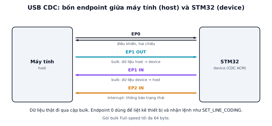
Figure 1. A CDC ACM device uses four endpoints: EP0 for control, a bulk IN and OUT pair for data, and an interrupt IN for notifications. Labels in the figure are in Vietnamese.
Endpoint 0 is for control: the host enumerates the device and sends class requests, such as setting the baud rate, through it. The real data goes through the bulk IN and OUT endpoints. A CDC device also has an interrupt IN endpoint for status notifications, which is hardly ever used in practice.
When plugged in, the host reads the descriptors (VID/PID, class, endpoints) and picks a driver. Windows 10 and later include a CDC driver; older versions need a driver file. The device shows up as a COM port on Windows or /dev/ttyACMx on Linux.
1.1. Speed
STM32 parts usually run Full-speed at 12 Mbit/s on the on-chip USB pins. A Full-speed bulk packet is at most 64 bytes, and according to the specification a 1 ms frame can carry about 19 bulk transactions of 64 bytes. The theoretical ceiling is therefore about 19 × 64 = 1216 bytes/ms, roughly 1.2 MB/s. Real numbers are lower and depend on the host, the operating system and the firmware. High-speed at 480 Mbit/s needs an external ULPI PHY on many families such as the F4, F7 and H7, though some H7 parts have an integrated High-speed PHY.
| Mode | Bit rate | Max bulk packet | Theoretical throughput |
|---|---|---|---|
| Full-speed | 12 Mbit/s | 64 bytes | about 1.2 MB/s (19 packets per 1 ms frame) |
| High-speed | 480 Mbit/s | 512 bytes | about 53 MB/s in theory |
Data travels over USB, not over a UART line, so the baud rate chosen on the computer has no effect on the real speed. The host just sends a SET_LINE_CODING request. The firmware can ignore it, or use it to configure a real UART when building a USB-UART bridge (section 4). Opening the port at 9600 or 115200 gives the same speed.
2. Configuration in STM32CubeIDE
| Step | Setting | Note |
|---|---|---|
| 1 | Enable USB_OTG_FS (or USB, depending on the family) in Device_Only mode | |
| 2 | Middleware: enable USB_DEVICE, Class For FS IP = Communication Device Class (Virtual Port Com) | |
| 3 | USB clock exactly 48 MHz | HSE + PLL, or HSI48 with CRS where available |
| 4 | Fill in VID/PID and descriptor strings | ST's default VID/PID is for testing only; commercial products need a valid VID/PID |
| 5 | Receive and transmit buffer sizes | 2048 bytes by default, adjust as needed |
| 6 | Generate Code | Cube generates usbd_cdc_if.c with the receive and transmit functions |
If the computer reports "Unknown USB Device", check the clock first. In the Clock Configuration tab, the "48MHz Clocks" box must read exactly 48 MHz. With an 8 MHz crystal, the PLL has to be set up so that both the desired SYSCLK and the 48 MHz branch come out as round numbers.
3. Source code
3.1. Sending data to the computer
#include "usbd_cdc_if.h"
#include <string.h>

// Returns USBD_BUSY if the previous transfer has not finished
uint8_t usb_print(const char *s)
{
    return CDC_Transmit_FS((uint8_t *)s, strlen(s));
}

// Send with retries so data is not lost while busy
int usb_send_retry(const uint8_t *p, uint16_t n, uint32_t timeout_ms)
{
    uint32_t t0 = HAL_GetTick();
    while (CDC_Transmit_FS((uint8_t *)p, n) == USBD_BUSY) {
        if (HAL_GetTick() - t0 > timeout_ms) return -1;
    }
    return 0;
}
CDC_Transmit_FS only accepts a new buffer once the previous packet has been sent; otherwise it returns USBD_BUSY. If the host has not opened the port or is not reading, usb_send_retry will time out, so always use a finite timeout.
3.2. Receiving with a ring buffer
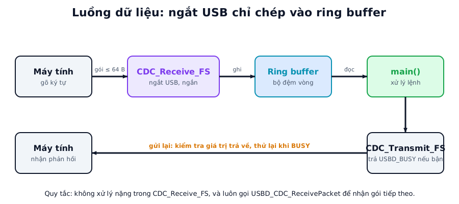
Figure 2. The USB interrupt only copies data into the ring buffer; the main loop processes it and sends the reply.
Modify the function Cube generated in usbd_cdc_if.c:
#define RB_SIZE 1024                                 // power of 2
static uint8_t rb[RB_SIZE];
static volatile uint16_t rb_head, rb_tail;

static void ring_write(const uint8_t *p, uint32_t n)
{
    while (n--) {
        uint16_t next = (rb_head + 1) & (RB_SIZE - 1);
        if (next == rb_tail) break;                  // full: drop the rest
        rb[rb_head] = *p++;
        rb_head = next;
    }
}

int ring_read(uint8_t *out)
{
    if (rb_tail == rb_head) return 0;
    *out = rb[rb_tail];
    rb_tail = (rb_tail + 1) & (RB_SIZE - 1);
    return 1;
}

static int8_t CDC_Receive_FS(uint8_t *Buf, uint32_t *Len)
{
    // Keep this function SHORT (it runs in USB interrupt context): only copy into the ring buffer
    ring_write(Buf, *Len);

    USBD_CDC_SetRxBuffer(&hUsbDeviceFS, &Buf[0]);
    USBD_CDC_ReceivePacket(&hUsbDeviceFS);           // required to keep receiving
    return USBD_OK;
}
Forget USBD_CDC_ReceivePacket at the end of the function and the device receives exactly one packet and then stops. Do heavy work in this function, such as printing logs, sending large blocks or waiting, and the USB interrupt is delayed and the host may report errors.
3.3. Example: echo in the main loop
while (1) {
    uint8_t c;
    while (ring_read(&c)) {
        // handle the command; here we just echo it back
        usb_send_retry(&c, 1, 10);
    }
}
Echoing byte by byte is easy to write but inefficient, because each byte becomes a USB transaction. For larger amounts of data, collect a block and send it at once, and check the return value.
3.4. Knowing when the computer has opened the port
To send logs only after the computer has opened the port (DTR asserted), handle the CDC_SET_CONTROL_LINE_STATE request in CDC_Control_FS:
static volatile uint8_t host_open;

// trong CDC_Control_FS(...):
case CDC_SET_CONTROL_LINE_STATE: {
    USBD_SetupReqTypedef *req = (USBD_SetupReqTypedef *)pbuf;
    host_open = (req->wValue & 0x0001) ? 1 : 0;      // bit 0: DTR
    break;
}
Then only call CDC_Transmit_FS when host_open is 1.
4. A USB-UART bridge
A common application: the computer sends commands through the virtual COM port, the STM32 forwards them to a real UART connected to an external device, and the same in the other direction.
From the computer, data arrives in CDC_Receive_FS, sits in the ring buffer, and the main loop sends it out of the UART with DMA. On the way back, the UART receives with DMA plus IDLE as in part 1, then calls CDC_Transmit_FS. To make the real UART speed follow the rate chosen on the computer, handle CDC_SET_LINE_CODING and reconfigure the UART.
5. Common faults
| Symptom | Usual cause | Fix |
|---|---|---|
| Computer does not recognise it ("Unknown USB Device") | USB clock not 48 MHz, D+/D− miswired, missing D+ pull-up on a custom board, charge-only cable | Check Clock Configuration, use a data cable, check the 1.5 kΩ D+ pull-up |
| Data lost when sending | CDC_Transmit_FS returned USBD_BUSY because the previous transfer was pending, return value ignored |
Check the return value and retry, or use a transmit queue |
| Only one packet received, then nothing | USBD_CDC_ReceivePacket missing in CDC_Receive_FS |
Restore the last two lines of the receive function |
| Hangs when sending with no host connected | Infinite wait while the host has not opened the port | Use a timeout, check host_open |
| Connection lost on sleep or reset | The USB device disappears and re-enumerates | Reopen the port on the computer side |
| COM port number differs between machines | The OS assigns port numbers | Identify the device by VID/PID and serial string, not the COM number |
| Throughput below expectations | Sending byte by byte, small buffers, slow main loop | Send large blocks, use a large transmit buffer, keep the loop fast |
| Breaks when other interrupts run | A higher-priority interrupt blocks the USB interrupt for too long | Set interrupt priorities sensibly |
6. Taking it into a product
In a product, take the USB clock from HSE through the PLL. On families with HSI48 and CRS (which locks to the USB SOF packets), the crystal can be dropped.
D+ and D− need protection: a TVS diode and small series resistors.
A product for sale needs a valid VID/PID, registered with USB-IF or obtained as a PID from a vendor, never ST's VID.
If you need more functions, CDC can be combined with another class such as HID or MSC in a composite device.
7. FAQ
Does it matter which baud rate I open the port with? No, the real transfer speed stays the same. It is just a parameter the computer sends down, which the firmware may use or ignore.
Does USB need an external crystal? Full-speed requires a 48 MHz clock with a very small tolerance, about ±0.25%. Families with HSI48 plus CRS can do without a crystal; others need HSE.
Does USB CDC keep working while the MCU sleeps? The device has to keep running to answer the host. Deep sleep drops the connection; only the suspend modes defined by the USB specification are usable.
CDC, HID or MSC? CDC for free-form serial data streams. HID for keyboard, mouse or gamepad-style devices, with no driver needed. MSC for storage devices.
8. Measurement plan
The "Measured" column stays empty until the code runs on hardware.
| Test | Method | Calculated | Measured |
|---|---|---|---|
| Time from plugging in to the COM port appearing | Measure on the computer | No calculated value | (to be filled) |
| Throughput from STM32 to the computer | Send 10 MB continuously, time it with a Python script | Theoretical ceiling about 1.2 MB/s | (to be filled) |
| Throughput from the computer to STM32 | As above, opposite direction | Theoretical ceiling about 1.2 MB/s | (to be filled) |
| Echo round-trip latency | Python script sends 1 byte, times the reply | Depends on the host, typically a few ms | (to be filled) |
| Data loss under heavy load | Send sequence-numbered data, verify | No loss if BUSY is handled correctly | (to be filled) |
| Byte-by-byte vs block transfers | Compare throughput with 1, 16, 64, 512-byte packets | Large blocks clearly faster | (to be filled) |
| USB packet capture | Wireshark with USBPcap, inspect bulk packets | 64-byte packets at Full-speed | (to be filled) |
Summary
If the device does not enumerate, check the 48 MHz clock first. Keep the receive function very short and push data into a ring buffer. When sending, always check for USBD_BUSY.
Part 10, the last one, moves on to Ethernet and TCP/IP: putting the STM32 on a network with LwIP, DHCP and a TCP echo server.
References
- ST documentation for the USB Device library (UM1734, STM32Cube USB device library)
- USB Device Class Definition for Communications Devices (usb.org)