Communication Protocols on STM32 (Part 6): RS-485 – differential signalling, termination and DE direction control
RS-485 on STM32, from differential signalling and bus wiring with termination and bias resistors (with calculated values) to switching the transceiver direction with the DE/RE pins, by GPIO or hardware Driver Enable. Part 6 of the Communication Protocols on STM32 series.
Note: the diagrams in this article were drawn by Capitlab for illustration. Table values are calculated from formulas; the "Measured" column will be filled in once measurements are made on hardware. The code was written from the HAL documentation and datasheets and has not yet been run on hardware, so verify it before using it in a product.
RS-485 is not a complete protocol, only a physical-layer standard: it defines voltage levels and wiring. The data on top is usually still UART, and above the UART sits an application protocol such as Modbus RTU (part 7). RS-485 is everywhere in automation because it reaches far, tolerates noise well and lets many devices share one pair of wires.
This part covers the three things you have to get right when putting RS-485 on an STM32: wiring with termination and bias resistors, connecting the transceiver, and switching between transmit and receive at the right moment so the last byte is not cut off.
1. How it works
RS-232 measures voltage against GND, so noise and ground differences between two devices go straight into the data. RS-485 sends two signals of opposite polarity on a twisted pair, and the receiver only looks at the difference between them. Noise couples into both wires almost equally (common-mode noise), so it disappears when one is subtracted from the other.
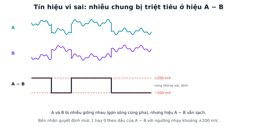
Figure 1. Common noise on A and B cancels in A − B. The receiver decides the logic level from the sign of A − B, with a threshold of about ±200 mV. Labels in the figure are in Vietnamese.
At low speeds (up to about 100 kbit/s) RS-485 reaches roughly 1200 m. The faster you go, the shorter the cable: at 10 Mbit/s only a few tens of metres. These are commonly quoted rules of thumb; the real limit depends on the cable and transceiver.
The original specification allows 32 unit loads on one bus. Reduced-load transceivers (1/4 or 1/8 unit load) allow more nodes.
The common configuration is half duplex: just two wires A and B, only one node transmitting at any moment, and a transceiver with DE (Driver Enable) and RE (Receiver Enable) pins to switch direction. Full duplex with two pairs also exists but is less common.
Manufacturers name the wires differently: some use D+ and D−, some swap A and B relative to others. If the wiring matches the diagram but nothing arrives, try swapping the two wires.
2. Wiring
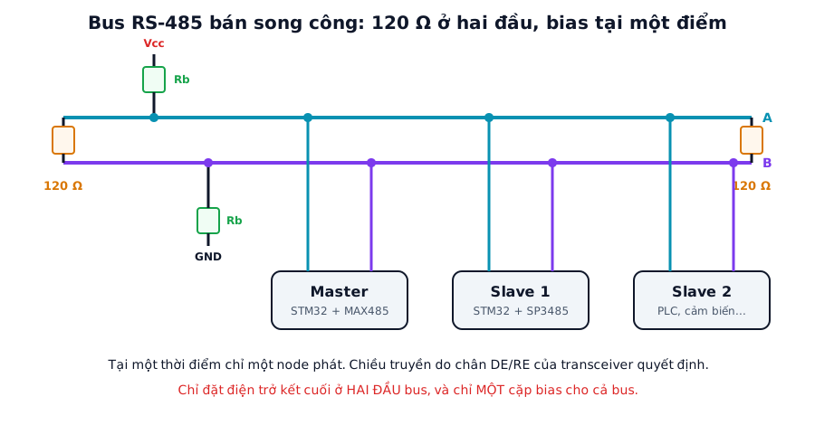
Figure 2. A typical RS-485 bus. Terminators at both ends and one pair of bias resistors at a single point (usually the master).
Use twisted-pair cable with a characteristic impedance of about 120 Ω, running from one node to the next (daisy chain). Avoid star wiring and long branches.
Fit a 120 Ω terminator at each end of the bus, and only at the ends. With power off, the resistance between A and B should be about 60 Ω.
When no node is transmitting the bus floats, and receivers may read garbage. A pair of bias (fail-safe) resistors pulls A to Vcc and B to GND so the idle bus always reads "1", i.e. A − B above +200 mV. One pair is enough for the whole bus, usually at the master. Many modern transceivers have fail-safe biasing built in.
The nodes need a common ground reference. In industrial settings the ground difference between cabinets can be large, and an isolated transceiver is the better choice.
Calculating the bias resistors
Idle bus voltage: VAB = Vcc × Rt / (2 × Rb + Rt), where Rt is the equivalent termination (two 120 Ω resistors in parallel, 60 Ω) and Rb is the bias resistor on each side. VAB must exceed the +200 mV threshold with some margin. Calculated values, not counting the receiver loads, which pull VAB down further:
| Vcc | Rb = 390 Ω | Rb = 470 Ω | Rb = 560 Ω | Rb = 680 Ω |
|---|---|---|---|---|
| 5 V | 357 mV | 300 mV | 254 mV | 211 mV |
| 3.3 V | 236 mV | 198 mV | 168 mV | 139 mV |
At Vcc = 3.3 V, Rb = 560 Ω or 680 Ω does not clear the 200 mV threshold. You need Rb around 390 Ω or lower, depending on the number of nodes. The trade-off is that a smaller Rb draws more idle current. Transceiver datasheets usually give a specific recommendation, so read it before choosing.
3. Connecting to the STM32
A transceiver (MAX485, SP3485, THVD1500, the isolated ADM2587E...) has four pins on the MCU side:
| Pin | Full name | Connect to |
|---|---|---|
| RO | Receiver Output | STM32 RX |
| DI | Driver Input | STM32 TX |
| DE | Driver Enable | GPIO (high = transmit) |
| RE | Receiver Enable (active low) | Usually tied to DE |
With DE and RE tied to one GPIO, high means transmit (DE on, RE off) and low means receive. As a bonus, the receiver is off while transmitting, so the node does not hear its own echo.
3.3 V transceivers (SP3485, THVD1500) connect directly to the STM32. A 5 V part such as the MAX485 drives RO at 5 V, so check whether the STM32 RX pin tolerates it; usually you add a level shifter or a divider.
4. Source code
4.1. Driving DE from a GPIO
#define RS485_TX_EN()  HAL_GPIO_WritePin(DE_GPIO_Port, DE_Pin, GPIO_PIN_SET)
#define RS485_RX_EN()  HAL_GPIO_WritePin(DE_GPIO_Port, DE_Pin, GPIO_PIN_RESET)

void rs485_send(const uint8_t *p, uint16_t n)
{
    RS485_TX_EN();
    HAL_UART_Transmit_IT(&huart2, (uint8_t *)p, n);
}

// Return to receive only when the last byte has left the shift register (TC), not TXE
void HAL_UART_TxCpltCallback(UART_HandleTypeDef *huart)
{
    if (huart == &huart2) RS485_RX_EN();
}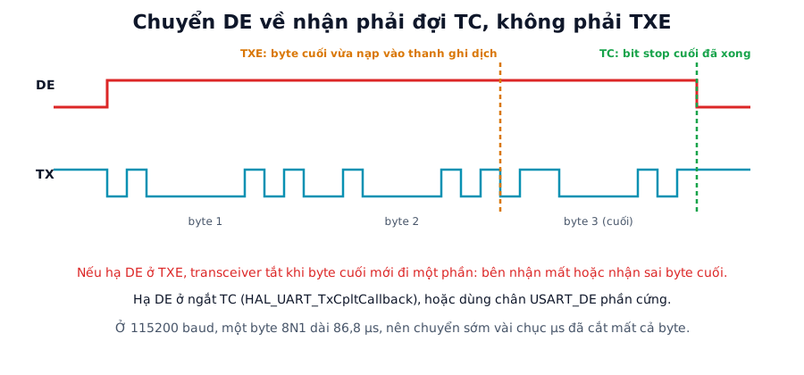
Figure 3. TXE fires when the last byte has just moved into the shift register and still has to be sent. TC fires when the final stop bit has left the pin. DE must drop at TC.
With HAL_UART_Transmit_IT or DMA, HAL calls HAL_UART_TxCpltCallback on the TC interrupt (transmission fully complete), so dropping DE in that callback is correct. If you write your own interrupt and drop DE as soon as the data register is empty (TXE), the last byte still in the shift register gets cut.
Calculated time for one 8N1 byte. At high speeds, switching about ten microseconds too early is enough to lose a whole byte:
| Baud rate | Time per byte (10 bits) |
|---|---|
| 9,600 | 1041.7 µs |
| 19,200 | 520.8 µs |
| 115,200 | 86.8 µs |
| 921,600 | 10.85 µs |
| 1,000,000 | 10.0 µs |
4.2. Receiving after transmitting
As soon as DE drops, the device must be ready to receive. If you use the DMA plus IDLE reception from part 1, leave reception running all the time and only switch the transceiver direction. With DE and RE tied together, the receiver is off while transmitting, so no echo ends up in the receive buffer.
4.3. USART hardware Driver Enable
Many STM32 families have a USARTx_DE pin: the hardware enables the transceiver during transmission, with configurable guard times before and after the frame. In CubeMX enable RS485 Hardware Flow Control (or initialise with HAL_RS485Ex_Init), choose the DE polarity and the assertion/de-assertion times in units of 1/16 bit, from 0 to 31. This is bit-accurate and independent of interrupt latency, so use it whenever the part supports it.
// Initialise instead of HAL_UART_Init (example):
if (HAL_RS485Ex_Init(&huart2, UART_DE_POLARITY_HIGH, 8, 8) != HAL_OK) Error_Handler();

// Then just transmit as usual; the hardware toggles DE:
HAL_UART_Transmit(&huart2, buf, len, 100);
5. Common faults
| Symptom | Usual cause | Fix |
|---|---|---|
| Garbage received while nobody transmits | No bias resistors, floating bus | Add a bias pair or use a fail-safe transceiver |
| Last byte of a packet lost | DE dropped at TXE instead of TC | Drop DE in HAL_UART_TxCpltCallback or use hardware USART_DE |
| Two nodes transmit at once, data corrupted | RS-485 has no arbitration like CAN | Use a master-slave request/response protocol so only one node talks |
| Errors at high speed or on long buses | Missing or extra terminators, long branches | Scope A-B, keep resistors only at the two ends |
| Nothing received despite correct wiring | A and B swapped because vendors label them differently | Try swapping A and B |
| One node brings down the whole bus | Faulty node stuck with DE asserted | Add a timeout (watchdog) that drops DE |
| Heavy noise, random frame loss | Untwisted cable, ground offsets | Shielded twisted pair, isolated transceiver |
6. Design notes
Keep stubs as short as possible, ideally zero, with every node sitting directly on the bus line.
In industrial environments the A and B pins need protection: series resistors, TVS diodes designed for RS-485, and gas discharge tubes where surges are a risk.
For long buses at high speed, choose a slew-rate limited transceiver to reduce ringing, and run only as fast as you need.
RS-485 has no arbitration, so the protocol on top has to decide who talks and when. Request/response protocols such as Modbus RTU also require a clear silent gap between frames.
7. Measurement plan
The "Measured" column stays empty until the code runs on hardware.
| Test | Method | Calculated | Measured |
|---|---|---|---|
| Bus resistance with power off | Multimeter between A and B | About 60 Ω | (to be filled) |
| Idle differential voltage A-B, with and without bias | Differential probe or two channels subtracted | As in the table in section 2 | (to be filled) |
| Waveforms at 9600, 115200 and 1 Mbaud, with and without terminators | Oscilloscope, look for ringing | Clear ringing without termination | (to be filled) |
| DE switching delay (GPIO vs hardware) | Logic analyzer: DE against TX | Hardware: per the configured assertion/de-assertion times | (to be filled) |
| Maximum distance at each speed | Increase cable length, note when errors start | Per the rules of thumb in section 1 | (to be filled) |
| Error rate with noise (near a motor or VFD) | Send 1 million bytes, count errors | No errors with good cable | (to be filled) |
8. FAQ
How does RS-485 differ from RS-232? RS-232 is point-to-point, referenced to GND (±3 to ±15 V) and short range. RS-485 is differential, multi-node, reaches much further and handles noise far better. Both usually carry UART data on top.
What is the difference between RS-485 and RS-422? RS-422 is also differential but has a single driver with several receivers, usually on two pairs in full duplex. RS-485 allows multiple drivers, so it can run half duplex on two wires.
Do short, slow buses need termination? A few metres at 9600 baud often works without it, but fitting terminators is still the safer choice. Long buses or high speeds require them.
Can Modbus run over RS-485? Yes, it is the most common use. See part 7: Modbus.
Summary
120 Ω terminators go only at the two ends, and one bias pair serves the whole bus. Drop DE on the TC interrupt, or use hardware USART_DE, so the last byte is not cut. RS-485 has no arbitration, so the protocol above it must decide who talks.
Part 7 builds Modbus RTU on top of RS-485: the frame, CRC-16 and the 3.5-character silent interval.
References
- TIA/EIA-485 and transceiver datasheets (MAX485, SP3485, THVD1500...)
- STM32 documentation on USART Driver Enable (
HAL_RS485Ex_Init) and the reference manual for your part