Communication Protocols on STM32 (Part 4): CAN and FDCAN – frames, arbitration and bit timing
CAN and CAN FD on STM32 (FDCAN), from the frame format, ID-based arbitration, bit timing calculation, frame time and bus load to HAL configuration, receive filters and bus-off recovery. Part 4 of the Communication Protocols on STM32 series.
Note: the diagrams in this article were drawn by Capitlab for illustration. Table values are calculated from formulas; the "Measured" column will be filled in once measurements are made on hardware. The code was written from the HAL documentation and datasheets and has not yet been run on hardware, so verify it before using it in a product.
CAN (Controller Area Network) was created for cars and is now found in industrial machines, robots and medical equipment. Differential signalling makes it robust against noise, the hardware detects errors and retransmits on its own, and many peer nodes share a single pair of wires.
STM32 has two kinds of CAN peripheral. Newer families (G0, G4, H5, H7, U5...) have FDCAN, which handles both classic CAN and CAN FD. Older ones such as the F1 and F4 have bxCAN, with a different set of HAL functions (HAL_CAN_*). This part is written for FDCAN.
A few things worth knowing up front. CAN has no node addresses: the ID describes the content of the message and sets its priority. The MCU only has logic-level TX/RX pins, so you need a transceiver plus two 120 Ω resistors at the ends of the bus. A node on its own can never complete a transmission because nobody sends the ACK, so when testing a single board use loopback mode.
1. How it works
1.1. Physical layer
CANH and CANL are twisted together, and the information is the voltage difference between them. The bus has two states: dominant (logic 0) and recessive (logic 1). When several nodes transmit at once, dominant always beats recessive. The lossless arbitration in section 1.3 relies on this.
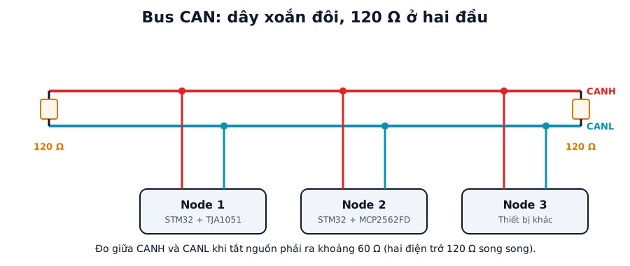
Figure 1. A typical CAN bus. Each node has an MCU and a transceiver (TJA1051, MCP2562FD...). The two 120 Ω resistors sit at the two ends of the bus. Labels in the figure are in Vietnamese.
With power off, the resistance between CANH and CANL should be about 60 Ω (two 120 Ω resistors in parallel). 120 Ω means one resistor is missing, a very high value means both are missing, and a very low value means a short or extra terminators. When the bus misbehaves, take this measurement first; it only needs a multimeter.
1.2. The classic CAN frame
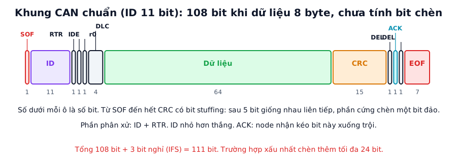
Figure 2. A standard CAN frame with an 11-bit ID and 8 data bytes: 108 bits (before stuffing), plus 3 bits of interframe space.
The ID is 11 bits in a standard frame and 29 bits in an extended frame. The 4-bit DLC gives the number of data bytes, from 0 to 8. A 15-bit CRC protects the frame, and the receiving nodes pull the ACK bit low to confirm reception.
After 5 identical bits in a row, the hardware inserts one bit of the opposite level so that the nodes stay synchronised (bit stuffing). The real length of a frame on the bus therefore depends on its content. Classic CAN runs at up to 1 Mbit/s.
1.3. Arbitration
When the bus is idle, any node may start transmitting. If two nodes start together, each one transmits and reads the bus back at the same time. A node that sends a recessive bit but reads dominant knows a higher-priority frame is on the bus, so it stops transmitting and switches to receiving. The winner's frame continues untouched.
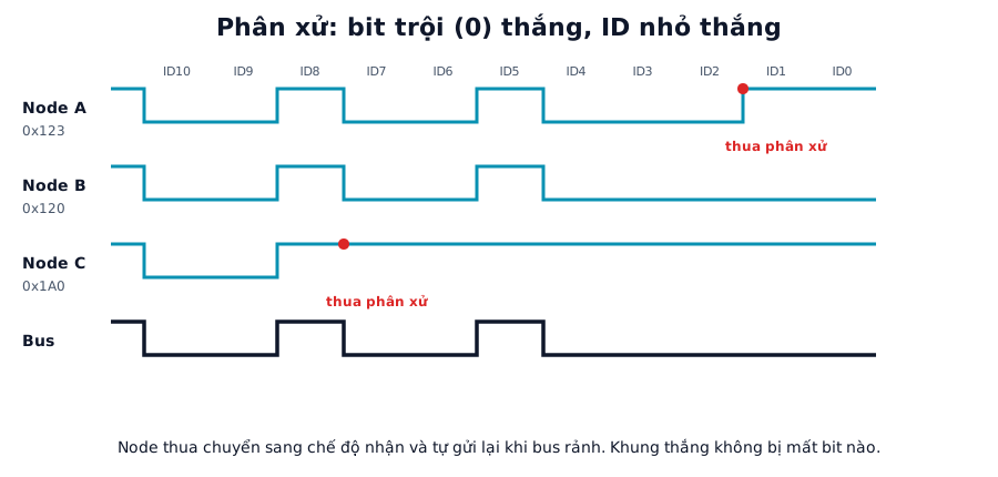
Figure 3. Three nodes transmitting together: C loses at bit ID7 (sends 1 but the bus is 0), A loses at bit ID1, and B with the lowest ID (0x120) wins.
This dictates how IDs are assigned: important messages (safety, real-time control) get low IDs, less urgent ones get high IDs. Never let two nodes send the same ID with different content.
1.4. Error detection and node states
CAN checks for errors at several levels: bit errors (comparing the sent bit with the read-back bit), stuff errors, CRC errors, form errors and ACK errors. Each node keeps two error counters, TEC for transmit and REC for receive, and is in one of three states:
| State | Condition | Behaviour |
|---|---|---|
| Error Active | TEC and REC both at most 127 | Normal; signals errors with a dominant error flag |
| Error Passive | TEC or REC above 127 | Signals errors with a recessive flag, must wait longer after transmitting |
| Bus-Off | TEC above 255 | Disconnected from the bus, neither sends nor receives |
A node with a hardware fault (wrong bit rate, broken wire) drives its TEC up quickly and drops into bus-off on its own, so it cannot take the whole bus down. To come back, it has to observe 128 sequences of 11 consecutive recessive bits on the bus.
1.5. CAN FD
CAN FD (Flexible Data-rate) carries up to 64 data bytes and can switch to a higher rate during the data phase (Bit Rate Switch, BRS). Arbitration still runs at the nominal rate, so CAN FD has two sets of bit timing parameters: Nominal and Data. The CRC is longer (17 or 21 bits), and the payload length can only be 0 to 8, 12, 16, 20, 24, 32, 48 or 64 bytes.
2. Bit timing
Each CAN bit is split into segments measured in time quanta (tq). The time quantum is the smallest time unit, obtained by dividing the peripheral clock by a prescaler:
Bit time = 1 tq (Sync) + TimeSeg1 + TimeSeg2
Bitrate = fdcan_ker_clk / (Prescaler × (1 + TimeSeg1 + TimeSeg2))
Sample point = (1 + TimeSeg1) / (1 + TimeSeg1 + TimeSeg2).
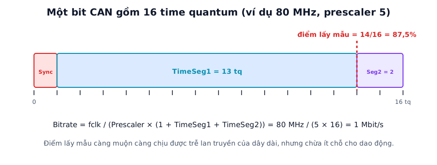
Figure 4. Example with an 80 MHz clock and prescaler 5: tq = 62.5 ns, 16 tq per bit gives 1 Mbit/s with the sample point at 87.5%.
Calculated for an 80 MHz peripheral clock, 16 tq per bit, TimeSeg1 = 13, TimeSeg2 = 2:
| Bit rate | Prescaler | tq | Sample point |
|---|---|---|---|
| 125 kbit/s | 40 | 500 ns | 87.5% |
| 250 kbit/s | 20 | 250 ns | 87.5% |
| 500 kbit/s | 10 | 125 ns | 87.5% |
| 1 Mbit/s | 5 | 62.5 ns | 87.5% |
The remaining parameter is SJW (Synchronization Jump Width), the maximum correction applied at each resynchronisation. It is usually 1 to 4 tq and must not exceed TimeSeg2. Every node on the bus must use the same bit rate, and the sample point should sit somewhere between 80 and 87.5%.
For an accurate bit rate, take the clock from a crystal (HSE), not an internal oscillator. Many Nucleo boards have no HSE crystal and take their clock from the ST-LINK instead, so check the actual configuration. Choose an FDCAN clock that is a multiple of the bit rate so the number of tq per bit is an integer.
For CAN FD the transceiver must handle the data-phase rate (the MCP2562FD goes up to 8 Mbit/s). The cable must be twisted pair, terminated with 120 Ω at both ends, with stubs kept as short as possible.
ST's documentation has a reference example on the STM32H753 with a 120 MHz FDCAN clock and prescaler 1. The 1 Mbit/s nominal phase uses 120 tq per bit, NominalTimeSeg1 = 101, NominalTimeSeg2 = 18, giving a sample point of about 85%. The 8 Mbit/s data phase uses 15 tq per bit, DataTimeSeg1 = 8, DataTimeSeg2 = 6, giving about 60%.
3. Frame time and bus load
A standard frame has 47 + 8n bits, where n is the number of data bytes, including the 3 interframe bits but not stuff bits. In the worst case stuffing adds up to ⌊(34 + 8n − 1) / 4⌋ bits. Calculated values:
| Data bytes | Bits (no stuffing) | Bits (worst case) | Time at 500 kbit/s | Time at 1 Mbit/s | Max frames/s at 500 kbit/s |
|---|---|---|---|---|---|
| 0 | 47 | 55 | 94 to 110 µs | 47 to 55 µs | 9,090 to 10,638 |
| 1 | 55 | 65 | 110 to 130 µs | 55 to 65 µs | 7,692 to 9,090 |
| 2 | 63 | 75 | 126 to 150 µs | 63 to 75 µs | 6,666 to 7,936 |
| 4 | 79 | 95 | 158 to 190 µs | 79 to 95 µs | 5,263 to 6,329 |
| 8 | 111 | 135 | 222 to 270 µs | 111 to 135 µs | 3,703 to 4,504 |
Use the table to estimate bus load. For example, ten 8-byte frames every 10 ms, i.e. 1000 frames/s, at 500 kbit/s take 1000 × 111 / 500,000 = 22% to 27% of the bandwidth. In automotive work the bus load is usually kept below roughly 30 to 50% to leave room for low-priority frames and error recovery.
4. Configuration in STM32CubeIDE
| Setting | Value | Note |
|---|---|---|
| Clock Divider | Per clock tree | FDCAN clock from PLL or HSE, see Clock Configuration |
| Frame Format | Classic Mode, FD no BRS or FD with BRS | |
| Mode | Normal (or Internal Loopback for testing) | |
| Auto Retransmission | Enable | Retransmit after lost arbitration or errors |
| Nominal Prescaler / Time Seg1 / Time Seg2 / SJW | From the table in section 2 | |
| Data Prescaler / Time Seg1 / Time Seg2 | Only for FD with BRS | |
| Std Filters Nbr | Number of 11-bit ID filters needed | |
| Tx FIFO Queue Elements | e.g. 8 | |
| NVIC | FDCAN1 interrupt 0 | Enable for interrupt-driven reception |
5. Source code
5.1. Initialisation and receive filter
CubeMX generates MX_FDCAN1_Init. What you add is the filter, the interrupts and the start call:
FDCAN_FilterTypeDef f = {0};
f.IdType       = FDCAN_STANDARD_ID;
f.FilterIndex  = 0;
f.FilterType   = FDCAN_FILTER_MASK;
f.FilterConfig = FDCAN_FILTER_TO_RXFIFO0;
f.FilterID1    = 0x120;
f.FilterID2    = 0x7F0;               // mask: accept IDs 0x120 to 0x12F
HAL_FDCAN_ConfigFilter(&hfdcan1, &f);

// Frames matching no filter: reject
HAL_FDCAN_ConfigGlobalFilter(&hfdcan1, FDCAN_REJECT, FDCAN_REJECT,
                             FDCAN_FILTER_REMOTE, FDCAN_FILTER_REMOTE);

HAL_FDCAN_ActivateNotification(&hfdcan1, FDCAN_IT_RX_FIFO0_NEW_MESSAGE, 0);
HAL_FDCAN_Start(&hfdcan1);
In FDCAN_FILTER_MASK mode, every bit set to 1 in the mask must match the corresponding bit of FilterID1 in the received ID. A mask of 0 (FilterID1 = 0, FilterID2 = 0) accepts every ID. A mask of 0x7FF accepts exactly one ID.
5.2. Sending a frame
FDCAN_TxHeaderTypeDef tx = {0};
uint8_t data[8] = {1, 2, 3, 4, 5, 6, 7, 8};

tx.Identifier          = 0x123;
tx.IdType              = FDCAN_STANDARD_ID;
tx.TxFrameType         = FDCAN_DATA_FRAME;
tx.DataLength          = FDCAN_DLC_BYTES_8;
tx.ErrorStateIndicator = FDCAN_ESI_ACTIVE;
tx.BitRateSwitch       = FDCAN_BRS_OFF;
tx.FDFormat            = FDCAN_CLASSIC_CAN;
tx.TxEventFifoControl  = FDCAN_NO_TX_EVENTS;
tx.MessageMarker       = 0;

if (HAL_FDCAN_AddMessageToTxFifoQ(&hfdcan1, &tx, data) != HAL_OK) {
    // FIFO full or peripheral not started
}
This call only places the frame in the queue; arbitration and transmission are handled by the peripheral. To know when the frame has gone out, enable FDCAN_IT_TX_COMPLETE.
5.3. Receiving in the callback
void HAL_FDCAN_RxFifo0Callback(FDCAN_HandleTypeDef *h, uint32_t it)
{
    if (it & FDCAN_IT_RX_FIFO0_NEW_MESSAGE) {
        FDCAN_RxHeaderTypeDef rx;
        uint8_t d[64];
        while (HAL_FDCAN_GetRxFifoFillLevel(h, FDCAN_RX_FIFO0) > 0) {
            if (HAL_FDCAN_GetRxMessage(h, FDCAN_RX_FIFO0, &rx, d) != HAL_OK) break;
            // rx.Identifier is the ID, rx.DataLength is the DLC code (not a byte count)
            // DLC 0..8 means 0..8 bytes, DLC 9..15 means 12, 16, 20, 24, 32, 48, 64 bytes
        }
    }
}
DataLength in HAL is the code of an FDCAN_DLC_BYTES_n constant, not a byte count. Compare against those constants, or use a conversion table that matches your HAL version.
5.4. High-speed CAN FD
To use CAN FD with BRS, set Frame Format to "FD mode with BRS", fill in Data Prescaler and Data Time Seg, and change the header when sending:
tx.FDFormat      = FDCAN_FD_CAN;
tx.BitRateSwitch = FDCAN_BRS_ON;
tx.DataLength    = FDCAN_DLC_BYTES_64;
The element sizes in FDCAN message RAM (RxBufferSize, TxElmtSize) must also be large enough for 64 bytes; otherwise long frames are truncated or rejected.
5.5. Error monitoring and bus-off recovery
void can_check_bus(void)
{
    FDCAN_ProtocolStatusTypeDef ps;
    FDCAN_ErrorCountersTypeDef  ec;
    HAL_FDCAN_GetProtocolStatus(&hfdcan1, &ps);
    HAL_FDCAN_GetErrorCounters(&hfdcan1, &ec);

    if (ps.BusOff) {
        // The peripheral has stopped. Call Start to begin recovery
        // (waits for 128 sequences of 11 recessive bits on the bus).
        HAL_FDCAN_Start(&hfdcan1);
    }
    // ec.TxErrorCnt, ec.RxErrorCnt: watch these for early warning as errors rise
    // ps.ErrorPassive, ps.Warning: error state flags
}
Call this periodically, every 100 ms for instance, or from HAL_FDCAN_ErrorStatusCallback. Count how many times the node has gone bus-off and store the number; it is very useful when diagnosing problems in the field.
Without a second node, set Mode = FDCAN_MODE_INTERNAL_LOOPBACK (or EXTERNAL_LOOPBACK) to test the send, receive and filter code on a single board.
6. Common faults
| Symptom | Usual cause | Fix |
|---|---|---|
| Transmission never completes, error counters rise | Only one node on the bus (no ACK) or bit rate mismatch between nodes | Add a second node, check the bit rate, or use Loopback |
| Repeated bus-off | Wrong bit rate, missing 120 Ω terminator, CANH/CANL swapped, transceiver unpowered | Measure the bus resistance (60 Ω), check wiring and transceiver supply |
| Fine at 500 kbit/s, fails at 1 Mbit/s or FD | Inaccurate clock, poor sample point, long cable, long stubs | Use HSE, adjust Seg1/Seg2, shorten cable and stubs |
| Nothing received | Filter rejects the frames, interrupt or HAL_FDCAN_Start missing |
Check the filter, global filter and NVIC |
| Frames lost under high load | Receive FIFO full because processing is slow | Larger FIFO, keep the callback short, use an RTOS queue |
| Wrong data length with CAN FD | DLC code confused with byte count, element size too small | Use the DLC table, configure 64-byte elements |
| HAL FDCAN on an F4 chip | F1 and F4 have bxCAN, not FDCAN | Use HAL_CAN_* for bxCAN |
7. Designing a CAN network
Run the bus as one line with a terminator at each end and short stubs to the nodes. Avoid star wiring. Use twisted-pair cable with a characteristic impedance of about 120 Ω, and connect the node grounds through a third wire or the enclosure if needed.
The higher the bit rate, the shorter the bus must be. Commonly quoted rule-of-thumb figures are about 40 m at 1 Mbit/s, 100 m at 500 kbit/s and 500 m at 125 kbit/s, but always verify them with your actual cable and environment.
In industrial environments, TVS diodes and a common-mode choke help against interference. For CAN FD on long buses or at high rates, choose a transceiver with SIC (signal improvement capability).
8. Measurement plan
The "Measured" column stays empty until the code runs on hardware.
| Test | Method | Calculated | Measured |
|---|---|---|---|
| Bus resistance with power off | Multimeter between CANH and CANL | About 60 Ω | (to be filled) |
| Bit rate 500 kbit/s | Oscilloscope, measure bit width | 2 µs per bit | (to be filled) |
| Actual sample point | Oscilloscope or logic analyzer with CAN decoding | 87.5% as configured | (to be filled) |
| Duration of an 8-byte frame at 500 kbit/s | Logic analyzer, SOF to end of EOF | 222 to 270 µs | (to be filled) |
| Maximum sustainable bus load | Send continuously, count frames at the other node | 3,703 frames/s (worst case) | (to be filled) |
| CAN FD: highest stable data-phase rate | Step through 2, 4, 5, 8 Mbit/s, record errors | Depends on transceiver and cable | (to be filled) |
| Priority arbitration | Two nodes send different IDs at once, see which wins | Lower ID wins | (to be filled) |
| Bus-off recovery time | Inject a fault on purpose, time the recovery | Depends on configuration and bus load | (to be filled) |
9. FAQ
Do CAN nodes need a shared clock? No. Each node has its own clock and resynchronises on the falling edge at the start of a frame and on stuff bits. That is why the clock must be accurate (crystal based), so that accumulated drift stays within SJW.
What is the difference between CAN 2.0A and 2.0B? 2.0A uses 11-bit IDs. 2.0B supports both 11-bit and 29-bit IDs. Both kinds can run on the same bus.
Can CAN FD coexist with classic CAN? A classic-only node will flag an error when it sees an FD frame. Use one type across the whole bus, or run the FD nodes in classic mode.
Can I skip the transceiver? No. The MCU only outputs logic levels. The transceiver produces the correct dominant and recessive voltages on the differential pair, tolerates noise and protects the MCU pins.
Summary
When the bus fails, measure the resistance between CANH and CANL before touching the software. Calculate the bit timing so the sample point lands around 80 to 87.5%, with a crystal clock. Watch the error counters and handle bus-off in the firmware.
Part 5 moves on to LIN: a cheap single-wire bus built on UART, widely used for auxiliary devices in cars, with its Break field, PID and checksum.
To decode CAN payloads quickly, try the Capitlab Hex Converter.
References
- STM32 FDCAN running at 8 Mb/s on Nucleo boards (ST Community)
- The reference manual for your STM32 (FDCAN chapter) and ST AN5348
- ISO 11898-1 and transceiver datasheets (TJA1051, MCP2562FD)