Communication Protocols on STM32 (Part 10): Ethernet and TCP/IP – MAC, PHY, RMII, LwIP and a TCP echo server
Ethernet on STM32, from the MAC, PHY and RMII architecture and LwIP and DHCP configuration to a TCP echo server using netconn, with calculated throughput figures and common faults. Part 10 of the Communication Protocols on STM32 series.
Note: the diagrams in this article were drawn by Capitlab for illustration. Table values are calculated from formulas; the "Measured" column will be filled in once measurements are made on hardware. The code was written from the HAL documentation and datasheets and has not yet been run on hardware, so verify it before using it in a product.
With Ethernet, a device gets an IP address and can do things like serve a configuration page to a browser, publish MQTT, run Modbus TCP or update its firmware over the network. The price is more hardware (MAC, PHY, a connector with magnetics) and a fairly heavy software protocol stack.
This part explains how the pieces fit together and then builds a TCP echo server. An echo server does little by itself, but it is the starting point for every other network application: once echo works, the hardware, driver and stack are all in order.
1. Architecture
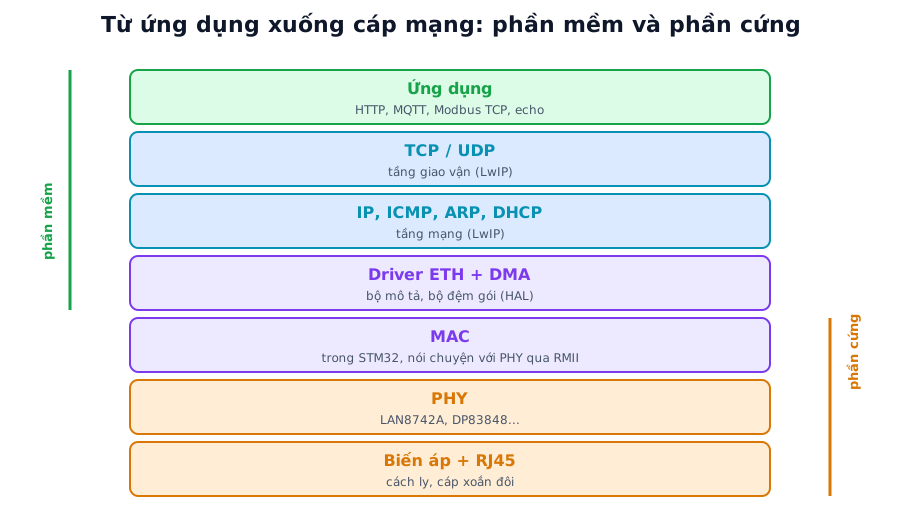
Figure 1. The Ethernet stack on STM32. Software is LwIP plus the ETH driver; hardware is the on-chip MAC, the PHY and the magnetics. Labels in the figure are in Vietnamese.
From the bottom up there are three layers.
The PHY is the physical-layer chip, for example the LAN8742A, DP83848 or KSZ8081. It connects to an RJ45 jack with magnetics and drives the signal onto 10/100 Mbit/s twisted-pair cable.
The MAC is a peripheral built into some STM32 families (F4, F7, H7, H5, U5...). It talks to the PHY over MII or RMII and uses DMA to move frames into memory.
On top sits the TCP/IP stack, the software that handles ARP, IP, ICMP (ping), UDP, TCP and DHCP. On STM32 the common choice is LwIP, which ships with Cube and usually runs alongside FreeRTOS.
STM32 parts without a MAC can still get on a network through an SPI Ethernet chip. The W5500 has a hardware TCP/IP stack; the ENC28J60 needs a software stack. Both are slower than an on-chip MAC.
1.1. The RMII connection
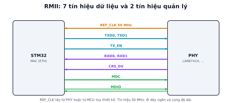
Figure 2. RMII uses 7 data signals and 2 management signals (MDC, MDIO).
RMII consists of REF_CLK (50 MHz, supplied by the PHY or the MCU depending on the design), TXD0/TXD1, TX_EN, RXD0/RXD1, CRS_DV, and the MDC/MDIO pair the MCU uses to read link state and speed from the PHY. These are 50 MHz signals, so the traces must be short and length-matched. The reference designs of the Nucleo and Discovery boards are a good guide. MII uses more pins (a 25 MHz clock, 4 bits in each direction) and is chosen less often.
2. Theoretical throughput
Besides the payload, every Ethernet frame on the wire carries an 8-byte preamble, a 14-byte header, a 4-byte FCS and a 12-byte interframe gap (IFG). Calculated values, not measurements:
| Quantity | Value |
|---|---|
| Minimum frame (64 bytes) plus 20 bytes of overhead | 84 bytes = 672 bits |
| Time for one minimum frame at 100 Mbit/s | 6.72 µs |
| Maximum minimum-size frames per second (100 Mbit/s) | 148,810 |
| Maximum minimum-size frames per second (10 Mbit/s) | 14,881 |
| One full TCP frame (MSS 1460 bytes) on the wire | 1538 bytes |
| Time for one full TCP frame at 100 Mbit/s | 123 µs |
| Theoretical maximum TCP payload throughput (100 Mbit/s) | about 94.9 Mbit/s ≈ 11.9 MB/s |
94.9 Mbit/s is the ceiling for application data in a stream of full TCP segments, after subtracting 38 bytes of Ethernet overhead (preamble, header, FCS, IFG), the 20-byte IP header and the 20-byte TCP header. A real STM32 reaches far less, because CPU time, the TCP window size and buffer memory all set limits. The real number has to be measured with iperf.
3. Configuration in STM32CubeIDE
| Step | Setting | Note |
|---|---|---|
| 1 | Enable ETH in RMII mode | Mode name depends on the family; check the pins match the board |
| 2 | Enable LWIP | Choose DHCP or a static IP |
| 3 | A unique MAC address | With several devices, one address each |
| 4 | Enable FreeRTOS (CMSIS_V2) | Needed for the socket or netconn API; without an RTOS use the raw API |
| 5 | PHY configuration | PHY address and the driver for the PHY on your board |
| 6 | Check clocks | Stable 50 MHz REF_CLK, enough MCU clock |
| 7 | LwIP memory | Heap size, number and size of packet buffers (PBUF) |
Once the cable is plugged in, the first test is to ping the STM32's IP from a computer. A successful ping means the PHY, MAC, driver and LwIP are all working. With DHCP the router assigns the IP, so print it on a UART to know what it is.
3.1. DHCP
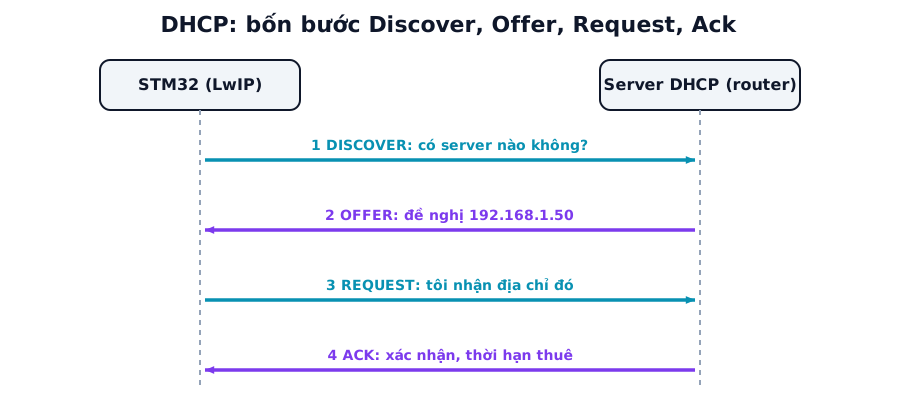
Figure 3. The four DHCP steps through which the device gets an IP address. LwIP handles all of them when DHCP is enabled.
The device broadcasts DISCOVER, the server answers with an OFFER proposing an address, the device sends REQUEST to take it, and the server replies ACK with the lease time.
DHCP only succeeds once the link is up. If DHCP starts before the cable is plugged in, it fails and has to be restarted. Unplugging and replugging the cable may also require restarting DHCP.
4. Source code: a TCP echo server with netconn
This runs in a FreeRTOS task after LwIP has initialised and obtained an IP:
#include "lwip/api.h"

void tcp_echo_task(void *arg)
{
    struct netconn *listener = netconn_new(NETCONN_TCP);
    netconn_bind(listener, IP_ADDR_ANY, 7);       // echo port
    netconn_listen(listener);

    for (;;) {
        struct netconn *client;
        if (netconn_accept(listener, &client) != ERR_OK) continue;

        struct netbuf *buf;
        while (netconn_recv(client, &buf) == ERR_OK) {
            void *data; u16_t len;
            do {
                netbuf_data(buf, &data, &len);
                netconn_write(client, data, len, NETCONN_COPY);   // send it back unchanged
            } while (netbuf_next(buf) >= 0);
            netbuf_delete(buf);
        }
        netconn_close(client);
        netconn_delete(client);
    }
}
From a computer, test with ncat <ip> 7 or telnet <ip> 7: whatever you type comes straight back. This code serves one connection at a time. For several simultaneous connections, create a task per connection or use the socket API with select.
4.1. From echo to Modbus TCP
Change the port to 502, strip the 7-byte MBAP header, process the PDU as in part 7, and reply with the same Transaction ID. A sample frame reading 2 registers: 00 01 00 00 00 06 01 03 00 00 00 02.
4.2. Testing tools on the computer
ping <ip> checks the network and basic latency. ncat <ip> 7 tests the echo. Wireshark shows all the ARP, DHCP and TCP handshake traffic between the computer and the STM32. iperf measures TCP throughput, with an iperf server running on the STM32 (LwIP includes an example).
5. Design notes
LwIP needs a heap and a pool of packet buffers (PBUF). Too little and packets are dropped; too much and RAM is wasted. Size them for the chip's RAM and the largest packets you need to receive.
On parts with a cache such as the F7 and H7, the MAC's DMA memory (descriptors and packet buffers) must sit in a non-cacheable region or be configured through the MPU. Otherwise packet data is corrupted in confusing ways, correct one moment and wrong the next.
Monitor the PHY link state over MDIO to know when the cable is unplugged or plugged back in, update the network interface state, and restart DHCP when the link comes up.
The LwIP task (tcpip_thread) and the driver's receive task need a high enough priority relative to other tasks, or packets will be dropped whenever the CPU is busy.
A networked device has to deal with security: authentication, encryption (TLS) and secure firmware updates. Close unused ports, and never expose Modbus TCP directly to the Internet.
6. Common faults
| Symptom | Usual cause | Fix |
|---|---|---|
| No ping | Wrong RMII pins, wrong PHY address, missing 50 MHz REF_CLK, no link (cable, magnetics, link LED) | Check step by step: link LED, REF_CLK on a scope, PHY registers over MDIO |
| Ping works but packets drop, slow | PBUF memory too small, low task priority, DMA cache issues | Larger pool, higher task priority, DMA buffers in non-cacheable memory |
| No IP from DHCP | Link not up when DHCP ran, router blocking | Wait for link before starting DHCP, try a static IP to rule things out |
| Duplicate MAC or IP | Several devices with the same default values | Give each device a unique MAC |
| Hangs after a while | Heap or stack overflow in the LwIP task | Increase stack size, check the FreeRTOS config, use heap statistics |
| Connects but drops immediately | Connection closed early, netconn_close misplaced, netbuf_delete missing |
Review the receive loop and buffer release |
| Fine on the bench, fails through a switch | Autonegotiation problems, poor cable | Check link speed/duplex, swap the cable |
7. FAQ
Ping works but TCP will not connect. Why? Ping uses ICMP and only needs the IP layer. TCP also needs large enough buffers, a properly running LwIP task, and no firewall on the computer blocking it. Open Wireshark and see whether the TCP handshake completes.
netconn, sockets or the raw API? The raw API is the fastest and leanest but hard to write, being event-driven and non-blocking. netconn and sockets are easier (blocking style) but need an RTOS. When starting out, use netconn or sockets.
How much RAM does it take? It depends on the configuration. LwIP on STM32 typically uses from a few tens of KB to over 100 KB for the heap and packet pools. Choose a part with enough RAM and keep an eye on the heap statistics.
W5500 or an on-chip MAC? The W5500 connects over SPI and runs the TCP/IP stack internally, saving RAM and software effort, but its speed is limited by SPI (part 2). An on-chip MAC is faster and more flexible, but needs a PHY and more careful hardware design.
8. Measurement plan
The "Measured" column stays empty until the code runs on hardware.
| Test | Method | Calculated | Measured |
|---|---|---|---|
| Time from power-up to obtaining an IP (DHCP) | From reset until the IP is printed | No calculated value | (to be filled) |
| Ping latency | ping repeatedly, record average and maximum |
Network dependent, usually under a few ms | (to be filled) |
| TCP throughput | iperf between the computer and STM32 in both directions |
Theoretical ceiling 94.9 Mbit/s | (to be filled) |
| CPU load at maximum throughput | GPIO in the idle task or RTOS statistics | No calculated value | (to be filled) |
| TCP echo round trip with small packets | Script timing send and receive | Network dependent | (to be filled) |
| Maximum simultaneous connections | Open many connections to the server, note when it fails | Memory dependent | (to be filled) |
| Packet analysis | Wireshark: ARP, DHCP, TCP handshake | All four DHCP steps present | (to be filled) |
| Recovery after unplugging the cable | Unplug for 10 seconds, replug, time the reconnection | Depends on link handling | (to be filled) |
Summary
A successful ping is the first sign that the hardware is right. On the F7 and H7, deal with the cache for DMA memory. Size LwIP's memory for your application instead of leaving the defaults.
This is the last part of the series, which went from a single UART wire through SPI, I²C, CAN, LIN, RS-485, Modbus, 1-Wire and USB to TCP/IP. These protocols are often used together. A familiar example is a Modbus TCP to RTU gateway: the STM32 receives requests over Ethernet and forwards them onto an RS-485 bus.
References
- ST documentation on LwIP for STM32 (AN3966 for F4/F2) and the Ethernet chapter of your part's reference manual
- LwIP documentation (savannah.nongnu.org/projects/lwip)
- PHY datasheets (LAN8742A, DP83848...)