Communication Protocols on STM32 (Part 3): I²C – addresses, pull-up resistors and register reads
I²C on STM32, from START, ACK and STOP and sizing pull-up resistors from bus capacitance to scanning the bus, reading sensor registers with HAL and recovering a stuck bus. Part 3 of the Communication Protocols on STM32 series.
Note: the diagrams in this article were drawn by Capitlab for illustration. Table values are calculated from formulas; the "Measured" column will be filled in once measurements are made on hardware. The code was written from the HAL documentation and datasheets and has not yet been run on hardware, so verify it before using it in a product.
I²C (Inter-Integrated Circuit) needs only two wires for a whole bus of devices, which is why it turns up in sensors, EEPROMs, RTCs and small OLED displays. In exchange it is slower than SPI and very sensitive to the pull-up resistors. When a bus scan finds nothing, the culprit is almost always one of three things: the address, the pull-ups or the wiring.
This part covers the frame, sizing pull-ups according to the specification, HAL code for scanning the bus and reading registers, and how to recover the bus when SDA is held low.
1. How it works
I²C has two wires: SCL (clock, driven by the master) and SDA (data, bidirectional). Both are open-drain: a device can only pull the line low, and the high level comes from a pull-up resistor. Because nothing drives the line high, many devices can share the bus without shorting each other when two of them transmit at once.
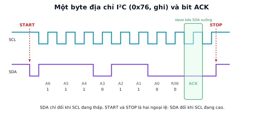
Figure 1. Address byte 0x76 with the write bit (R/W = 0). SDA may only change while SCL is low, except for START and STOP. Labels in the figure are in Vietnamese.
A transfer consists of:
- START: SDA falls while SCL is high.
- The address byte: 7 address bits and one read/write bit (R/W, 0 for write, 1 for read).
- ACK: the addressed device pulls SDA low on the 9th clock.
- Data bytes, each followed by an ACK bit. When reading, the master answers the last byte with NACK to say it has enough.
- STOP: SDA rises while SCL is high. Or a repeated START to change direction without releasing the bus.
Every byte costs 9 clocks (8 bits plus ACK). Calculated times for the standard modes:
| Mode | Max rate | Time per byte (9 clocks) | One register read (about 36 clocks) |
|---|---|---|---|
| Standard-mode | 100 kbit/s | 90 µs | 360 µs |
| Fast-mode | 400 kbit/s | 22.5 µs | 90 µs |
| Fast-mode Plus | 1 Mbit/s | 9 µs | 36 µs |
These are calculated values, excluding START, STOP and software overhead. The standard also has High-speed mode (3.4 Mbit/s), which is rare on STM32.
Reading a register
The most common transaction is a sensor register read: write the register address, issue a repeated START to switch to reading, then receive the data. HAL_I2C_Mem_Read does exactly this.
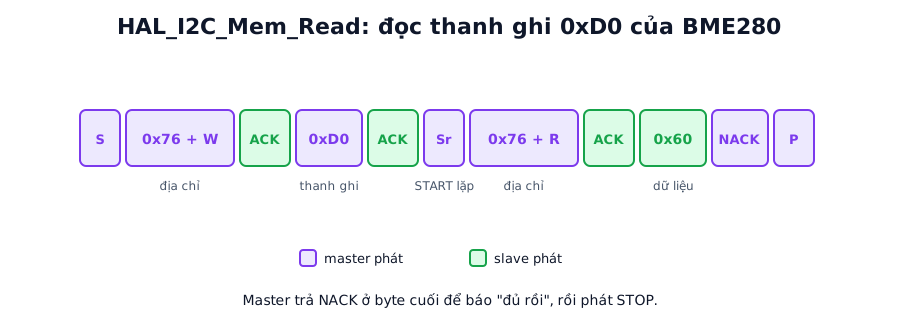
Figure 2. Reading the BME280 ID register. Purple boxes are driven by the master, green by the slave. 0x60 is the BME280 ID according to the datasheet.
2. Choosing the pull-up resistors
The pull-ups decide how fast the rising edge is. The I²C specification (UM10204) gives two limits:
- Upper:
Rp(max) = Trise / (0.8473 × Cbus), where Trise is the maximum rise time allowed for the mode (measured from 30% to 70% of VDD) and Cbus is the total bus capacitance. - Lower:
Rp(min) = (VDD − VOL(max)) / IOL, where IOL is the sink current the devices can handle. With VDD = 3.3 V, VOL = 0.4 V and IOL = 3 mA this gives about 0.97 kΩ.
Rp(max) calculated with the maximum Trise from the specification: 1000 ns (Standard), 300 ns (Fast), 120 ns (Fast-mode Plus):
| Bus capacitance Cbus | Rp(max) Standard 100 kHz | Rp(max) Fast 400 kHz | Rp(max) Fast Plus 1 MHz |
|---|---|---|---|
| 50 pF | 23.6 kΩ | 7.08 kΩ | 2.83 kΩ |
| 100 pF | 11.8 kΩ | 3.54 kΩ | 1.42 kΩ |
| 200 pF | 5.90 kΩ | 1.77 kΩ | 0.71 kΩ |
To use the table you first need an estimate of Cbus. Each device pin adds a few pF and every 10 cm of wire adds a few tens of pF. Datasheets give pin capacitance; for the wiring it is better to measure. Then pick a resistor between Rp(min) and Rp(max). For a 100 pF bus at 400 kHz, 2.2 kΩ is a sensible choice: below 3.54 kΩ and above 0.97 kΩ. If Rp(max) comes out smaller than Rp(min), the bus cannot meet the specification at that speed; lower the speed, reduce the capacitance or split the bus.
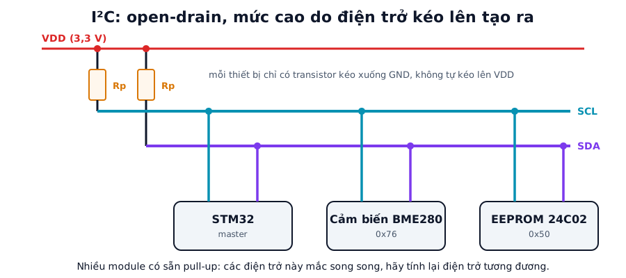
Figure 3. A typical I²C bus. Each device only pulls to GND; the high level comes from Rp.
Many breakout modules already carry pull-ups, usually 4.7 kΩ or 10 kΩ. Plug several of them onto one bus and those resistors end up in parallel, so the equivalent value keeps dropping, sometimes below Rp(min). Recalculate and remove some if needed.
The MCU's internal pull-ups are typically a few tens of kΩ. They are fine for a quick test but should not be used in a product.
3. Configuration in STM32CubeIDE
| Setting | Value | Note |
|---|---|---|
| Mode | I2C | |
| I2C Speed Mode | Standard or Fast | |
| Clock Speed | 100000 or 400000 | G0, G4, L4, H7... use the TIMING register, calculated by CubeMX |
| Addressing Mode | 7-bit | |
| GPIO | Open-drain | Set automatically by CubeMX for I2C pins |
| Pull-up | None (external resistors) | Internal pull-ups for testing only |
4. Source code
4.1. Scanning the bus
This lists every device that answers with ACK. HAL expects the 7-bit address shifted left by one:
void i2c_scan(void)
{
    for (uint8_t addr = 1; addr < 128; addr++) {
        if (HAL_I2C_IsDeviceReady(&hi2c1, addr << 1, 2, 10) == HAL_OK) {
            printf("Tim thay thiet bi: 0x%02X\r\n", addr);
        }
    }
}
printf has to be retargeted to a UART before it prints anything. UART setup is covered in part 1.
4.2. Reading and writing registers
Example: reading the ID register 0xD0 of a BMP280/BME280. The address is 0x76 or 0x77 depending on the SDO pin. A BMP280 returns 0x58, a BME280 returns 0x60:
#define BME_ADDR  (0x76 << 1)

HAL_StatusTypeDef bme_read_id(uint8_t *id)
{
    return HAL_I2C_Mem_Read(&hi2c1, BME_ADDR, 0xD0,
                            I2C_MEMADD_SIZE_8BIT, id, 1, 100);
}

HAL_StatusTypeDef bme_write_reg(uint8_t reg, uint8_t val)
{
    return HAL_I2C_Mem_Write(&hi2c1, BME_ADDR, reg,
                             I2C_MEMADD_SIZE_8BIT, &val, 1, 100);
}
EEPROMs with 16-bit memory addresses (24C32 and up) need I2C_MEMADD_SIZE_16BIT. After each EEPROM write the chip needs time for its internal write cycle and will not ACK during it. Call HAL_I2C_IsDeviceReady repeatedly until it ACKs again.
For large blocks there are HAL_I2C_Mem_Read_DMA and HAL_I2C_Mem_Read_IT, which signal completion through HAL_I2C_MemRxCpltCallback.
4.3. Error handling
Check the return value of every HAL call and read the error code when it fails:
HAL_StatusTypeDef st = bme_read_id(&id);
if (st != HAL_OK) {
    uint32_t err = HAL_I2C_GetError(&hi2c1);
    if (err & HAL_I2C_ERROR_AF)    { /* NACK: wrong address or device busy */ }
    if (err & HAL_I2C_ERROR_BERR)  { /* bus error: misplaced START or STOP */ }
    if (err & HAL_I2C_ERROR_ARLO)  { /* arbitration lost */ }
    if (st == HAL_TIMEOUT)         { /* bus held, see the stuck-bus recovery section */ }
}
5. Recovering a stuck bus
The symptoms: HAL calls return HAL_BUSY forever, or SDA measures low. A common cause is the MCU resetting in the middle of a transaction while the slave is driving a 0 bit and holding SDA. The slave only releases SDA once it has shifted out the rest of that byte, so the master has to supply extra clocks to let it finish:
- De-initialise the I²C peripheral (
HAL_I2C_DeInit). - Configure SCL and SDA as open-drain GPIO outputs.
- Send up to 9 pulses on SCL, stopping once SDA reads high.
- Generate a STOP (SDA rising while SCL is high).
- Re-initialise the I²C peripheral.
// PB6 = SCL, PB7 = SDA (I2C1), example
static void i2c_bus_recover(void)
{
    GPIO_InitTypeDef g = { .Pin = GPIO_PIN_6 | GPIO_PIN_7,
                           .Mode = GPIO_MODE_OUTPUT_OD,
                           .Pull = GPIO_NOPULL, .Speed = GPIO_SPEED_FREQ_LOW };
    HAL_I2C_DeInit(&hi2c1);
    HAL_GPIO_Init(GPIOB, &g);
    HAL_GPIO_WritePin(GPIOB, GPIO_PIN_6 | GPIO_PIN_7, GPIO_PIN_SET);

    for (int i = 0; i < 9 && HAL_GPIO_ReadPin(GPIOB, GPIO_PIN_7) == GPIO_PIN_RESET; i++) {
        HAL_GPIO_WritePin(GPIOB, GPIO_PIN_6, GPIO_PIN_RESET); HAL_Delay(1);
        HAL_GPIO_WritePin(GPIOB, GPIO_PIN_6, GPIO_PIN_SET);   HAL_Delay(1);
    }
    // STOP
    HAL_GPIO_WritePin(GPIOB, GPIO_PIN_7, GPIO_PIN_RESET);     HAL_Delay(1);
    HAL_GPIO_WritePin(GPIOB, GPIO_PIN_6, GPIO_PIN_SET);       HAL_Delay(1);
    HAL_GPIO_WritePin(GPIOB, GPIO_PIN_7, GPIO_PIN_SET);       HAL_Delay(1);

    MX_I2C1_Init();                       // init function generated by CubeMX
}
If SDA is still low after 9 pulses, the device has locked up completely or the line is shorted. The only options left are cutting the device's power or pulling its reset pin low, if it has one.
6. Common faults
| Symptom | Usual cause | Fix |
|---|---|---|
| Scan finds nothing | Address not shifted left, missing pull-ups, SCL/SDA swapped, wrong address (module ADDR/SDO pin) | Probe SCL/SDA with a logic analyzer, check pull-ups, try neighbouring addresses |
| NACK error (AF) | Wrong address or device busy (e.g. EEPROM writing) | Check the address, poll with HAL_I2C_IsDeviceReady |
| Works at 100 kHz, fails at 400 kHz | Pull-ups too large or long wires (large Cbus) | Measure the rising edge on a scope, lower the resistance, shorten wires |
Constant HAL_BUSY or timeouts |
Bus stuck, SDA held low | Run the recovery procedure in section 5 |
| Two devices with the same address | Same sensor type twice on one bus | Change the address-select pin or use an I²C multiplexer (e.g. TCA9548A) |
| Strange data | Wrong register address size (8 vs 16 bit), wrong byte order | Check the datasheet, change I2C_MEMADD_SIZE_* |
| Faults with a 5 V device on a 3.3 V MCU | Pull-ups to 5 V push SDA/SCL beyond the MCU pin rating | Use an I²C level shifter, or pull up to 3.3 V |
7. A few more details
A slave is allowed to hold SCL low to make the master wait (clock stretching). The STM32 I²C peripheral handles this, and in slave mode it can be disabled with the No Stretch Mode option. If you bit-bang I²C on GPIOs, check that SCL has really gone high before continuing.
Some devices have a bus timeout: SMBus specifies roughly 25 to 35 ms. If SCL is held low longer than that, the device resets its interface, so don't leave a transaction stalled halfway for long.
Some addresses are reserved, such as 0x00 (general call) and the range 0x78 to 0x7F. A bus scan sometimes shows "mystery devices" there.
8. Measurement plan
The "Measured" column stays empty until the code runs on hardware.
| Test | Method | Calculated | Measured |
|---|---|---|---|
| Actual SCL frequency at 100 kHz and 400 kHz | Logic analyzer | 100 kHz and 400 kHz (timing chosen by CubeMX) | (to be filled) |
| SDA/SCL rise time with Rp = 1 kΩ, 2.2 kΩ, 4.7 kΩ, 10 kΩ | Oscilloscope, 30% to 70% of VDD | From Rp × Cbus × 0.8473 |
(to be filled) |
| Largest resistor still reliable at 400 kHz | Increase resistance step by step, note when errors start | 100 pF bus: below 3.54 kΩ | (to be filled) |
| Time for one register read | Logic analyzer, START to STOP | 90 µs at 400 kHz | (to be filled) |
| Bus recovery with 9 clocks | Hold SDA low with a helper device, run the procedure, observe | SDA high within 9 pulses | (to be filled) |
| Parallel pull-ups from several modules | Measure the equivalent resistance from SDA to VDD | Parallel value of the resistors | (to be filled) |
9. FAQ
7-bit or 8-bit address, and why does every source differ? The I²C specification uses 7-bit addresses. Some datasheets quote an "8-bit" address that already includes the R/W bit. STM32 HAL wants the 7-bit address shifted left by one, so 0x76 is written 0x76 << 1, which is 0xEC.
How many devices can share one bus? Addressing allows 128, minus the reserved addresses. The real limit is bus capacitance, at most 400 pF per the specification, together with the matching pull-up value.
How long can an I²C bus be? I²C is meant for connections on one board or a few tens of centimetres. Beyond that you need lower speed, a bus extender chip, or a move to RS-485 or CAN.
Interrupt or DMA? For a few bytes, polling is enough. For periodic block reads, such as 100 bytes from an IMU, DMA frees the CPU, as long as you implement the error and timeout callbacks.
Summary
Always fit pull-ups and size them for the bus capacitance. Shift the 7-bit address left when calling HAL. Product firmware should include a bus recovery routine.
Part 4 moves on to CAN and FDCAN: a differential multi-master bus with filters, ACK and built-in error detection, widely used in cars and industry.
To decode sensor data quickly, try the Capitlab Hex Converter.
References
- What Are I2C Pull-Up Resistors and How to Calculate Their Values (Total Phase)
- I²C-bus specification and user manual (UM10204, NXP)
- BME280/BMP280 datasheet (Bosch Sensortec) and the STM32 HAL documentation (
HAL_I2C_*functions)