Communication Protocols on STM32 (Part 7): Modbus RTU and TCP – frames, CRC-16 and the 3.5-character silence
Modbus RTU and Modbus TCP on STM32, from the data model, frame structure and CRC-16 (with verified examples) to the 3.5-character silent interval and slave code using DMA and the IDLE interrupt. Part 7 of the Communication Protocols on STM32 series.

Note: the diagrams in this article were drawn by Capitlab for illustration. Table values are calculated from formulas; the "Measured" column will be filled in once measurements are made on hardware. Example frames and CRCs were checked with a program. The code was written from the HAL documentation and datasheets and has not yet been run on hardware, so verify it before using it in a product.
Modbus dates from 1979 and is still the common language of industrial equipment: PLCs, drives, energy meters, sensors. It is simple, the specification is open, and almost every device supports it. The two variants you will meet are RTU, a binary format over serial links such as RS-485, and TCP, over Ethernet.
When you write your own Modbus slave, the two classic mistakes are sending the CRC bytes in the wrong order and getting register addresses off by one. This part includes CRC-checked example frames to compare against, plus how to detect RTU frame boundaries with DMA and the IDLE interrupt on an STM32.
1. Data model
Modbus is request/response: the master (client) asks, the slave (server) answers, and a slave never transmits on its own. Data in a device is split into four areas:
| Area | Type | Access | Common function codes |
|---|---|---|---|
| Coils | 1 bit | Read/write | 0x01 read, 0x05 write single, 0x0F write multiple |
| Discrete Inputs | 1 bit | Read only | 0x02 |
| Holding Registers | 16 bit | Read/write | 0x03 read, 0x06 write single, 0x10 write multiple |
| Input Registers | 16 bit | Read only | 0x04 |
In RTU each slave has an address from 1 to 247. Address 0 is broadcast: every slave executes the command but none replies.
Values wider than 16 bits (32-bit integers, floats) are built from two or more consecutive registers. The standard does not define the order of those registers (word order), so every vendor does it their own way. To decode quickly, paste the bytes into the Hex Converter, which shows all four orders ABCD, DCBA, BADC and CDAB at once.
2. Modbus RTU
2.1. The frame
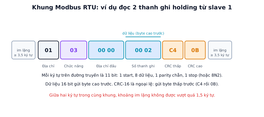
Figure 1. An RTU frame. Frames are at most 256 bytes long and are surrounded by at least 3.5 characters of silence. Labels in the figure are in Vietnamese.
| Slave address | Function code | Data | CRC16 (low) | CRC16 (high) |
|---|---|---|---|---|
| 1 byte | 1 byte | N bytes | 1 byte | 1 byte |
On the wire each character is usually 11 bits: 1 start, 8 data, 1 even parity, 1 stop. Without parity, use 8N2 to keep 11 bits. 16-bit data goes high byte first (big-endian), but the CRC goes low byte first.
2.2. Verified example: reading 2 holding registers
Reading 2 holding registers from slave 1 starting at address 0. The request is 01 03 00 00 00 02 C4 0B:
01is the slave address,03is read holding registers.00 00is the start address,00 02the number of registers.C4 0Bis the CRC, low byteC4first, high byte0Bsecond.
If the two registers hold 0x0012 and 0x0034, the response is 01 03 04 00 12 00 34 5B E1. Here 04 is the number of data bytes that follow and 5B E1 is the CRC. The CRC of both frames was calculated with a program for reference.
A write example: setting register address 1 of slave 1 to 3 with function 0x06 is 01 06 00 01 00 03 98 0B. On success the slave echoes the request frame back unchanged.
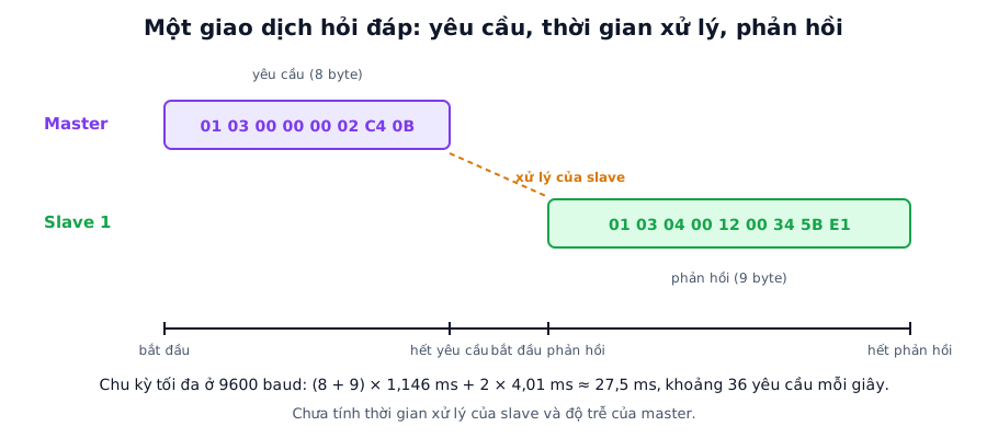
Figure 2. One request/response exchange. There is always silence between frames, and the slave needs processing time before it answers.
2.3. Exception responses
When a slave cannot carry out a request, it returns the function code with its high bit set (0x03 becomes 0x83) plus one exception code byte. For example, slave 1 reporting an illegal data address for a holding register read: 01 83 02 C0 F1.
| Code | Meaning |
|---|---|
| 01 | Illegal function |
| 02 | Illegal data address |
| 03 | Illegal data value |
| 04 | Slave device failure |
2.4. Modbus CRC-16
Polynomial 0x8005, written bit-reversed as 0xA001, initial value 0xFFFF, no final inversion:
uint16_t modbus_crc16(const uint8_t *p, uint16_t n)
{
    uint16_t crc = 0xFFFF;
    while (n--) {
        crc ^= *p++;
        for (int i = 0; i < 8; i++)
            crc = (crc & 1) ? (crc >> 1) ^ 0xA001 : crc >> 1;
    }
    return crc;   // send the low byte (crc & 0xFF) first, then the high byte (crc >> 8)
}
Check: the bytes 31 32 33 34 35 36 37 38 39 ("123456789") must give 0x4B37. You can compare with the Capitlab CRC calculator using CRC-16/MODBUS. If the firmware needs more speed, replace the bit-by-bit loop with a 256-entry lookup table.
2.5. Frame boundaries are defined by time
RTU has no start or end character. The boundary between frames is silence on the line:
- Between two frames there must be at least 3.5 character times of silence.
- Within a frame, two consecutive characters must not be more than 1.5 character times apart, or the frame is treated as broken.
- One character time is the number of bits divided by the baud rate.
- Above 19200 baud the specification allows fixed values: 750 µs for 1.5 characters and 1750 µs for 3.5 characters, because the calculated values become too short to implement.
Calculated for 11-bit characters. The cycle column is the theoretical time for one read of two registers: an 8-byte request, a 9-byte response and two 3.5-character silences, excluding slave processing time:
| Baud rate | 1 character | 1.5 characters | 3.5 characters | Theoretical minimum cycle | Reads per second |
|---|---|---|---|---|---|
| 9,600 | 1.146 ms | 1.72 ms | 4.01 ms | 27.5 ms | 36 |
| 19,200 | 0.573 ms | 0.86 ms | 2.01 ms | 13.7 ms | 72 |
| 38,400 | 0.286 ms | 0.75 ms (fixed) | 1.75 ms (fixed) | 8.4 ms | 119 |
| 115,200 | 0.095 ms | 0.75 ms (fixed) | 1.75 ms (fixed) | 5.1 ms | 195 |
Reading many registers at once is far cheaper than reading them one by one. Reading 125 registers (the maximum for function 0x03) takes about 301 ms at 9600 baud and about 25 ms at 115200 baud, only about 2.4 ms and 0.2 ms per register.
On an STM32 the natural way to detect the end of a frame is the UART IDLE interrupt together with DMA (part 1). At high speeds IDLE (one character) arrives before the 3.5-character mark, but it is still enough to conclude that the frame is over, because within a valid frame bytes are never more than 1.5 characters apart. At low speeds, or when you need to follow the specification strictly, use a 3.5-character timer that restarts on every received byte.
2.6. Slave processing skeleton
#define MY_ADDR 1

// When the UART signals end of frame (IDLE) with an rx buffer of length len:
void modbus_on_frame(const uint8_t *rx, uint16_t len)
{
    if (len < 4) return;                                     // too short
    uint16_t crc = modbus_crc16(rx, len - 2);
    if (rx[len-2] != (crc & 0xFF) || rx[len-1] != (crc >> 8)) return;   // bad CRC: ignore, do not reply
    if (rx[0] != MY_ADDR && rx[0] != 0) return;              // not addressed to us

    switch (rx[1]) {
    case 0x03: handle_read_holding(rx, len); break;
    case 0x06: handle_write_single(rx, len); break;
    case 0x10: handle_write_multiple(rx, len); break;
    default:   send_exception(rx[0], rx[1], 0x01); break;     // unsupported function code
    }
}
A sample handler for function 0x03, where regs[] is the device's holding register table:
static uint16_t regs[100];

static void handle_read_holding(const uint8_t *rx, uint16_t len)
{
    uint16_t addr = (rx[2] << 8) | rx[3];
    uint16_t qty  = (rx[4] << 8) | rx[5];
    if (qty < 1 || qty > 125)              { send_exception(rx[0], 0x03, 0x03); return; }
    if (addr + qty > 100)                  { send_exception(rx[0], 0x03, 0x02); return; }

    uint8_t tx[5 + 250];
    uint16_t k = 0;
    tx[k++] = rx[0]; tx[k++] = 0x03; tx[k++] = qty * 2;
    for (uint16_t i = 0; i < qty; i++) {
        tx[k++] = regs[addr + i] >> 8;     // high byte first
        tx[k++] = regs[addr + i] & 0xFF;
    }
    uint16_t crc = modbus_crc16(tx, k);
    tx[k++] = crc & 0xFF;                  // CRC: low byte first
    tx[k++] = crc >> 8;
    if (rx[0] != 0) rs485_send(tx, k);     // no reply to broadcast
}
rs485_send and DE pin control are covered in part 6. The slave only switches to transmit once the request frame has ended, and goes back to receive as soon as it has finished sending, so it is ready for the next request.
Plenty of open-source Modbus libraries exist for STM32. A library is faster to deploy, but writing one yourself once makes the timing and CRC rules above much clearer.
3. Modbus TCP
Modbus TCP keeps the data model and function codes and only replaces the transport with TCP/IP on port 502. Instead of the slave address and CRC, a frame carries a 7-byte MBAP header. The CRC is no longer needed because TCP already guarantees data integrity.
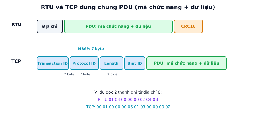
Figure 3. RTU and TCP share the PDU (function code and data); only the wrapper differs.
| Field | Size | Meaning |
|---|---|---|
| Transaction ID | 2 bytes | Matches requests with responses |
| Protocol ID | 2 bytes | Always 0 |
| Length | 2 bytes | Number of remaining bytes (Unit ID + PDU) |
| Unit ID | 1 byte | Replaces the slave address, used by gateways to RTU |
The rest is the PDU (function code and data), identical to RTU. Reading 2 registers from address 0: 00 01 00 00 00 06 01 03 00 00 00 02. The 00 06 field counts the 6 remaining bytes: Unit ID, function code and 4 data bytes.
On an STM32 you need a TCP/IP stack, covered in part 10. The simple approach is a socket server listening on port 502: receive the frame, strip the MBAP, process the PDU, and reply with an MBAP that carries the same Transaction ID. TCP-to-RTU gateways usually use the Unit ID to pick the RTU slave behind them.
4. Common faults
| Symptom | Usual cause | Fix |
|---|---|---|
| No response | Wrong slave address, wrong baud rate or parity, DE direction wrong | Check both sides' settings, compare frames with a logic analyzer |
| Response rejected for bad CRC | CRC bytes swapped, or CRC computed over bytes outside the frame | Send the CRC low byte first, check against the C4 0B example |
| Frame split in two | Silence too short, IDLE splitting packets early, bytes too far apart | Check the DMA/IDLE or timer logic, send each frame in one go |
| Wrong register address | Device manual numbers from 1 (e.g. 40001), frames use 0-based addresses | Subtract one and drop the 4xxxx prefix when building the frame |
| Wrong float values | Word order of the two registers differs between vendors | Try ABCD, DCBA, BADC, CDAB in the Hex Converter |
| Master reports timeout | Slave too slow, master timeout too short | Increase the timeout, speed up processing |
| Two slaves with the same address | Duplicate configuration | Give each device a unique address |
5. Practical notes for slaves
To test a slave, use master software on a PC such as Modbus Poll or QModMaster with a USB-RS485 adapter. It is the quickest way to compare frames one by one.
A slave that receives a frame with a bad CRC must not answer, not even with an exception. The frame may just be noise, or it may be addressed to another device.
An RTU frame is at most 256 bytes, so one read covers at most 125 registers (function 0x03) and one write at most 123 registers (function 0x10). When designing the register map, put values that are read together into one contiguous block so the master can fetch them in a single request.
6. FAQ
Does Modbus have encryption or authentication? The original protocol does not; commands and data travel in clear text. Never expose Modbus TCP directly to an outside network. There is a Modbus/TCP Security variant using TLS, but few devices support it.
RTU or TCP? RTU is cheap, reuses the RS-485 cabling already in a plant and is stable over long distances, but slow. TCP is fast, uses Ethernet infrastructure and allows several masters at once, but the device needs a network port and a TCP/IP stack.
Can Modbus RTU run over USB? Yes, through a USB-to-RS485 adapter (which appears as a virtual COM port), or by implementing the slave directly on the STM32's USB CDC.
How does Modbus ASCII differ from RTU? ASCII uses text characters, starts each frame with a colon and checks it with an LRC. It is easy to read by eye but half the speed of RTU, which is why RTU is more common.
7. Measurement plan
The "Measured" column stays empty until the code runs on hardware.
| Test | Method | Calculated | Measured |
|---|---|---|---|
| Compare frames with master software (Modbus Poll or similar) | Send 01 03 00 00 00 02, compare the response and CRC |
Response 01 03 04 ... 5B E1 with the sample data |
(to be filled) |
| Actual 3.5-character silence at 9600 and 115200 | Logic analyzer | 4.01 ms and 1.75 ms | (to be filled) |
| Response time (end of request to start of response) | Logic analyzer | Depends on slave processing | (to be filled) |
| Two-register reads per second at each speed | Count in the master software | 36 at 9600, 195 at 115200 (theoretical maximum) | (to be filled) |
| Reading 125 registers: time per transaction | Logic analyzer or master software | 301 ms at 9600, 25 ms at 115200 | (to be filled) |
| Behaviour on a deliberately bad CRC | Send a frame with a broken CRC, watch the slave | No response | (to be filled) |
| Modbus TCP: request/response latency | Wireshark or a TCP master tool | Depends on the network and stack | (to be filled) |
Summary
The CRC goes low byte first. RTU frame boundaries are defined by silence, which makes DMA plus the IDLE interrupt a good fit on STM32. Read data in blocks to make good use of the bandwidth.
Part 8 moves on to 1-Wire: the single-wire protocol of the DS18B20 temperature sensor, where time slots of a few microseconds decide whether a read succeeds.
To check a CRC or decode a float spread over two registers, try the Capitlab CRC calculator and Hex Converter.
References
- MODBUS RTU Frame Detection for MCU Implementation
- Modbus RTU CRC-16 Calculation: Algorithm and Implementation Guide
- Modbus Application Protocol Specification, Modbus over Serial Line, Modbus Messaging on TCP/IP Implementation Guide (modbus.org)