Communication Protocols on STM32 (Part 5): LIN – Break field, PID and checksum
LIN on STM32 using the USART, from the frame structure (Break, Sync, PID, data, checksum) and step-by-step PID and checksum examples to frame timing and HAL code for master and slave. Part 5 of the Communication Protocols on STM32 series.
Note: the diagrams in this article were drawn by Capitlab for illustration. Table values are calculated from formulas; the "Measured" column will be filled in once measurements are made on hardware. PID and checksum examples were checked with a program. The code was written from the HAL documentation and datasheets and has not yet been run on hardware, so verify it before using it in a product.
LIN (Local Interconnect Network) is a cheap, slow, single-wire bus used in cars for auxiliary devices such as mirrors, seats, windows and rain sensors, the places where CAN would be overkill. At heart LIN is a UART with a frame structure and master-slave rules on top, so the STM32 runs it naturally on a USART. Most of the groundwork is in part 1 on UART.
A LIN network has one master and several slaves (typically up to 16 nodes), one data wire plus GND, and runs at 1 to 20 kbit/s, most often 19.2 kbit/s. Slaves only speak when the master asks them to.
1. How it works
1.1. Network and physical layer
The master coordinates the network with a schedule table: a list of frames, in order, each with its own time slot. Slaves cannot transmit on their own; they only answer when a header carries an ID they are responsible for. Since nobody competes for the bus, LIN needs no arbitration like CAN. The price is low speed, which suits auxiliary devices only.
Bus levels follow the battery, around 12 V, so a transceiver between the MCU and the LIN wire is mandatory.
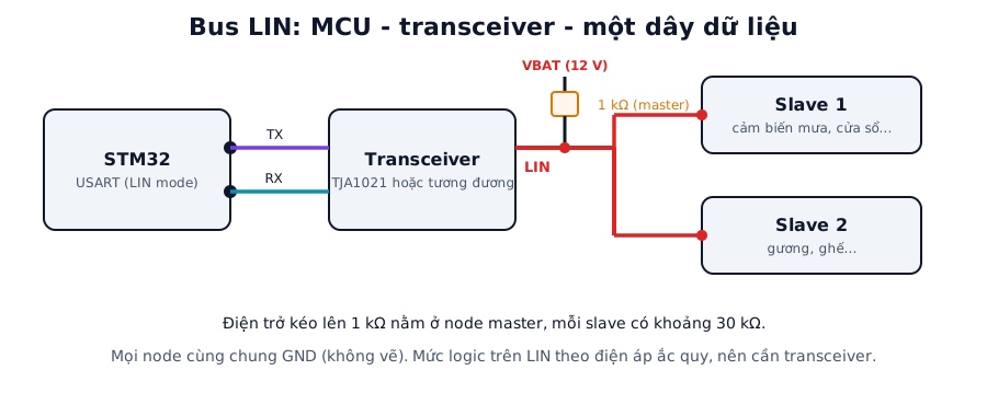
Figure 1. The MCU connects to the LIN transceiver through the USART TX and RX pins. The single LIN wire has a pull-up to VBAT at the master node. Labels in the figure are in Vietnamese.
1.2. The LIN frame
Each frame consists of a header sent by the master and a response sent by the master or one slave, depending on the ID:
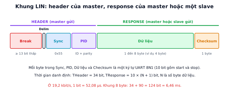
Figure 2. A LIN frame. The Break is long enough for slaves to recognise the start of a frame, Sync (0x55) lets them re-measure the bit rate, and the PID says what the frame is.
| Field | Content |
|---|---|
| Break | Line held low for at least 13 bit times, then released high for at least 1 bit time (delimiter). Marks the start of a frame |
| Sync | The byte 0x55. Slaves time this run of alternating bits to synchronise their baud rate |
| PID | 6 ID bits plus 2 parity bits |
| Data | 1 to 8 bytes |
| Checksum | 1 byte |
Nominal timing: THeader = 34 bits and TResponse = 10 × (N + 1) bits, where N is the number of data bytes. The specification allows a frame to stretch up to 1.4 times the nominal value. Calculated values, excluding the gaps between frames:
| Data bytes | Total bits | 9.6 kbit/s | 19.2 kbit/s | Maximum allowed at 19.2 kbit/s (× 1.4) |
|---|---|---|---|---|
| 1 | 54 | 5.63 ms | 2.81 ms | 3.94 ms |
| 2 | 64 | 6.67 ms | 3.33 ms | 4.67 ms |
| 4 | 84 | 8.75 ms | 4.38 ms | 6.13 ms |
| 8 | 124 | 12.92 ms | 6.46 ms | 9.04 ms |
Each slot in the schedule table must fit the maximum frame time (× 1.4), not the nominal one. Otherwise the next frame runs into the previous one.
1.3. PID and parity
The ID is 6 bits (0 to 63). The two parity bits are computed from the ID bits:
P0 = ID0 ⊕ ID1 ⊕ ID2 ⊕ ID4P1 = NOT (ID1 ⊕ ID3 ⊕ ID4 ⊕ ID5)
PID = ID (bits 0 to 5) | P0 << 6 | P1 << 7. Slaves check the parity and ignore the whole header if it is wrong.
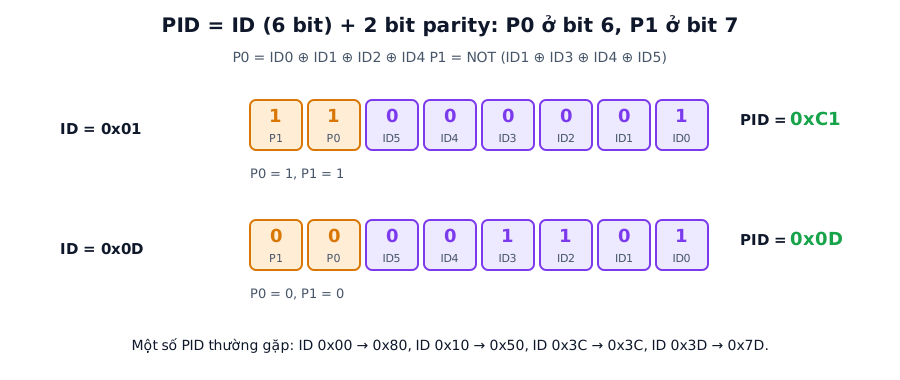
Figure 3. Two PID examples. ID 0x01 has both parity bits set, so its PID is 0xC1. ID 0x0D has both clear, so its PID stays 0x0D.
Some common PIDs, checked with a program: ID 0x00 gives 0x80, 0x10 gives 0x50, 0x3C (master diagnostic frame) gives 0x3C, 0x3D (slave diagnostic frame) gives 0x7D.
1.4. Checksum
The LIN checksum is an inverted sum with carry wrap-around: add the bytes, subtract 255 whenever the sum exceeds 255 (which adds the carry back in), then take the bitwise NOT. There are two variants:
- Classic: only the data bytes are summed. This is the LIN 1.x method.
- Enhanced: the PID is summed together with the data bytes. LIN 2.x added it, but diagnostic frames (IDs 0x3C and 0x3D) still use classic.
Some devices only support classic, so when connecting an unfamiliar device, check its documentation for the variant it uses.
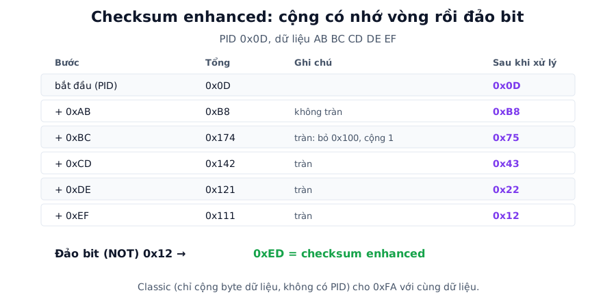
Figure 4. Enhanced checksum step by step. The result is 0xED. The same data with the classic method (no PID) gives 0xFA.
You can check it yourself with the Capitlab CRC / checksum calculator by choosing LIN enhanced or classic.
2. STM32 configuration
Many STM32 families have a LIN mode built into the USART: the hardware generates the break when sending and detects it when receiving. HAL provides HAL_LIN_Init and HAL_LIN_SendBreak.
| Setting | Value | Note |
|---|---|---|
| Mode | LIN (Asynchronous with LIN) | Select in CubeMX if the part supports it |
| Baud Rate | 19200 | The usual LIN rate |
| Word Length | 8 Bits | |
| Parity | None | LIN parity lives in the PID, not in the UART |
| Stop Bits | 1 | |
| Break detect length | 10 or 11 bits | Break detection threshold on the receive side |
| Clock | Use HSE | LIN has a tight speed tolerance |
If the part has no LIN mode, a plain UART still works. Drop the baud rate to about 9/13 of the normal rate, send 0x00, then restore the baud rate. The start bit plus eight 0 bits make 9 low bits at the slow rate, which is longer than 13 bits at the normal rate.
3. Source code
3.1. Computing the PID and checksum
static uint8_t lin_pid(uint8_t id)
{
    uint8_t b[6];
    for (int i = 0; i < 6; i++) b[i] = (id >> i) & 1;
    uint8_t p0 = b[0] ^ b[1] ^ b[2] ^ b[4];
    uint8_t p1 = !(b[1] ^ b[3] ^ b[4] ^ b[5]);
    return (id & 0x3F) | (p0 << 6) | (p1 << 7);
}

static uint8_t lin_checksum(uint8_t pid, const uint8_t *d, uint8_t n, int enhanced)
{
    uint16_t sum = enhanced ? pid : 0;
    for (uint8_t i = 0; i < n; i++) {
        sum += d[i];
        if (sum > 0xFF) sum -= 0xFF;
    }
    return (uint8_t)(~sum);
}
Quick check: lin_pid(0x01) must equal 0xC1, and lin_checksum(0x0D, {AB,BC,CD,DE,EF}, 5, 1) must equal 0xED (0xFA for classic).
3.2. The master sends a frame
void lin_master_send(uint8_t id, const uint8_t *data, uint8_t n)
{
    uint8_t pid = lin_pid(id);
    uint8_t frame[2 + 8 + 1];
    uint8_t k = 0;
    frame[k++] = 0x55;                    // Sync
    frame[k++] = pid;                     // PID
    for (uint8_t i = 0; i < n; i++) frame[k++] = data[i];
    frame[k++] = lin_checksum(pid, data, n, 1);

    HAL_LIN_SendBreak(&huart2);           // Break generated by the hardware
    HAL_UART_Transmit(&huart2, frame, k, 50);
}
For frames the slave has to answer, the master sends only Break, Sync and PID, then switches to receiving and waits for the response within the allowed time, at most 1.4 times the nominal value from section 1.2.
3.3. The slave receives the header
The slave has to recognise the Break, read Sync, read the PID and check its parity, then receive or send the response depending on the ID. The simplest structure is a state machine in the receive interrupt:
typedef enum { WAIT_BREAK, WAIT_SYNC, WAIT_PID, RX_DATA } lin_state_t;
static volatile lin_state_t st = WAIT_BREAK;
static uint8_t rx_byte, rx_buf[10], rx_n, rx_pid, want;

void USART2_IRQHandler(void)
{
    if (__HAL_UART_GET_FLAG(&huart2, UART_FLAG_LBD)) {   // break detected
        __HAL_UART_CLEAR_FLAG(&huart2, UART_CLEAR_LBDF); // flag name to clear depends on the family
        st = WAIT_SYNC;
    }
    HAL_UART_IRQHandler(&huart2);
}

void HAL_UART_RxCpltCallback(UART_HandleTypeDef *h)
{
    switch (st) {
    case WAIT_SYNC: if (rx_byte == 0x55) st = WAIT_PID; else st = WAIT_BREAK; break;
    case WAIT_PID:
        if (lin_pid(rx_byte & 0x3F) == rx_byte) {         // parity OK
            rx_pid = rx_byte; rx_n = 0; want = response_length(rx_byte & 0x3F);
            st = RX_DATA;
        } else st = WAIT_BREAK;
        break;
    case RX_DATA:
        rx_buf[rx_n++] = rx_byte;
        if (rx_n == want + 1) {                           // data + checksum
            if (lin_checksum(rx_pid, rx_buf, want, 1) == rx_buf[want]) { /* valid frame */ }
            st = WAIT_BREAK;
        }
        break;
    default: break;
    }
    HAL_UART_Receive_IT(&huart2, &rx_byte, 1);
}
response_length is a table you define yourself, mapping each ID to its byte count. The code only illustrates the flow. The break flag name (LBD or LBDF) and how to clear it differ between STM32 families, so check the reference manual. A real slave also has to re-measure the bit rate from the Sync byte, which is fiddly, so many projects use an existing LIN stack rather than writing their own.
4. Design notes
LIN tolerates only a small speed mismatch between nodes, so the master must run from a crystal, not an RC oscillator.
Pull-ups are typically 1 kΩ at the master and about 30 kΩ at each slave. The 30 kΩ is usually already inside the transceiver or module.
The LIN checksum is only a simple sum. If the data matters enough to need stronger error detection, use CAN.
5. Common faults
| Symptom | Usual cause | Fix |
|---|---|---|
| Slave does not recognise the header | Break too short (under 13 bit times at the sender), or wrong break detection length | Measure the Break with a logic analyzer, set 10 or 11 bits on the receiver |
| Checksum mismatch | Classic and enhanced mixed up, PID left out | Diagnostic frames use classic, normal frames use enhanced (LIN 2.x) |
| PID rejected | Parity computed wrongly | Check lin_pid: ID 0x01 must give 0xC1 |
| No signal on the bus | Transceiver has no 12 V supply, missing pull-up | Check the supply, measure the level on the LIN wire |
| Frames come and go | Speed mismatch between master and slave, unstable clock | Use a crystal for the master |
| Response arrives too late | Master closes the window too early | Allow up to 1.4 times the nominal time |
6. FAQ
How is LIN different from UART? The characters on the wire are identical to UART 8N1. LIN adds the Break, Sync, PID, checksum and the master-slave rules. The STM32 runs LIN on a USART, either with the hardware LIN mode or by generating the break manually.
Why is the Sync byte 0x55? 0x55 is 01010101b, full of consecutive edges. Slaves time the edges to work out the exact bit length and adjust their rate, which lets a slave running on an internal oscillator still receive correctly.
Can LIN replace RS-485? LIN is meant for short distances (inside a vehicle, about 40 m maximum per the specification) and low speeds. For longer or faster links, see RS-485 in part 6.
7. Measurement plan
The "Measured" column stays empty until the code runs on hardware.
| Test | Method | Calculated | Measured |
|---|---|---|---|
| Actual Break length | Logic analyzer, measure how long the line is low | At least 13 bit times = 677 µs at 19.2 kbit/s | (to be filled) |
| PID and checksum check | Compare the logic analyzer's LIN decode with calculated values | ID 0x01 → PID 0xC1, checksum 0xED (example above) | (to be filled) |
| Duration of an 8-byte frame | Logic analyzer, from Break to end of checksum | 6.46 ms at 19.2 kbit/s | (to be filled) |
| Stable schedule table period | Measure the time between consecutive headers | As configured in the schedule | (to be filled) |
| Waveform on the 12 V bus | Oscilloscope, observe levels and slew rate | Depends on the transceiver | (to be filled) |
| Tolerated master/slave speed mismatch | Detune the master gradually, note when the slave fails | Depends on the slave | (to be filled) |
Summary
LIN is a UART plus a master-slave frame. The Break must be at least 13 low bits, Sync 0x55 lets slaves lock onto the bit rate, and both sides must use the same checksum variant.
Part 6 moves on to RS-485: a differential half-duplex physical layer that underpins many industrial protocols, Modbus in particular.
References
- Introduction to the LIN Bus Protocol (NI)
- How to Implement LIN Protocol on STM32 Using UART (ControllersTech)
- LIN checksum (TI, SDAA220A)
- The LIN 2.x specification and transceiver datasheet (TJA1021)