Communication Protocols on STM32 (Part 1): UART – frames, baud rate and DMA reception with the IDLE interrupt
UART on STM32, from the frame format and baud rate error to receiving packets of unknown length with circular DMA and the IDLE interrupt. Includes diagrams, HAL code and a table of common faults. Part 1 of the Communication Protocols on STM32 series.
Note: the diagrams in this article were drawn by Capitlab for illustration. Table values are calculated from formulas; the "Measured" column will be filled in once measurements are made on hardware. The code was written from the HAL documentation and datasheets and has not yet been run on hardware, so verify it before using it in a product.
Almost every embedded project has at least one UART, even if it only prints a log. The protocol is simple, yet the annoying faults (dropped bytes, garbage characters, buffer overruns) usually come back to two questions: how far the real baud rate is from the one you asked for, and how the receiver knows that a packet has ended.
This part answers both on an STM32. The first half covers the frame and how to work out the baud rate error. The second half shows how to receive packets of any length with circular DMA plus the IDLE interrupt, including a detail that trips up a lot of people: the Size argument in the callback is the DMA write position, not the number of bytes just received.
1. The UART frame
UART is asynchronous: the two sides share no clock and agree on speed and format in advance. The idle line sits high. Each character is made of:
- One start bit, which pulls the line low.
- 5 to 9 data bits, least significant bit first. 8 bits is by far the most common.
- An optional even or odd parity bit.
- One or two stop bits, which return the line high.
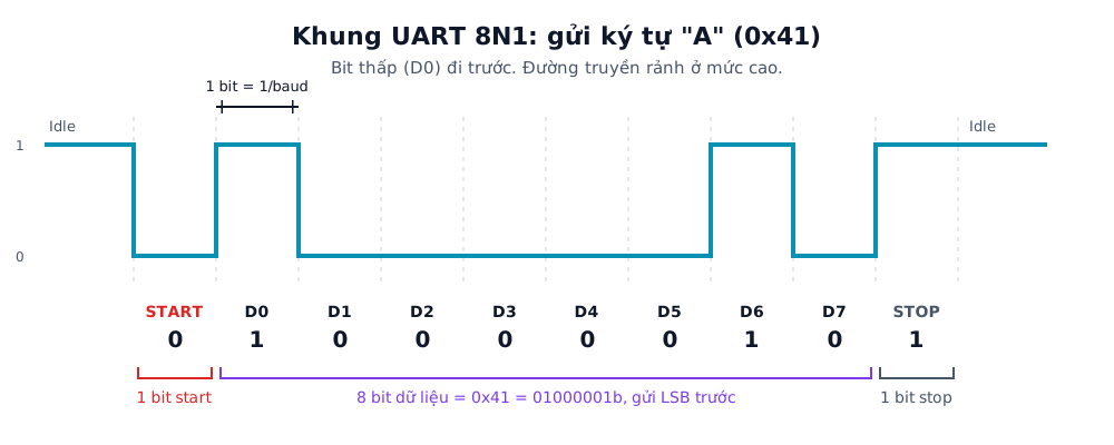
Figure 1. An 8N1 UART frame sending "A" (0x41 = 01000001b). D0 goes first, so the bits on the line are 1, 0, 0, 0, 0, 0, 1, 0. Labels in the figure are in Vietnamese.
The 8N1 format (8 data bits, no parity, 1 stop bit) spends 10 bits per byte. At 115200 baud the maximum throughput is therefore 11,520 bytes/s, not 14,400.
The receiver detects the falling edge of the start bit and then samples each bit near the middle of its period. If the two sides run at noticeably different speeds, the sampling point drifts, and by the last bit it lands in the neighbouring bit, which gives a framing error. For a 10-bit frame the theoretical limit on the combined mismatch is about 5%. In practice keep it under 2% to leave room for noise and slow edges.
2. Baud rate and error on STM32
The STM32 derives the baud rate by dividing the USART kernel clock (fck). With 16x oversampling (the default) the BRR register holds the divider in units of 1/16:
BRR ≈ fck / baud (rounded to an integer), and the actual baud rate = fck / BRR
Because BRR is an integer, the actual rate is rarely exactly what you asked for. The table below is calculated for fck = 84 MHz with 16x oversampling. These are calculated values, not measurements:
| Target baud rate | BRR | Actual baud rate | Error | Bit time | Max throughput (8N1) |
|---|---|---|---|---|---|
| 9,600 | 8750 | 9,600 | 0.000% | 104.17 µs | 960 bytes/s |
| 57,600 | 1458 | 57,613 | +0.023% | 17.36 µs | 5,760 bytes/s |
| 115,200 | 729 | 115,226 | +0.023% | 8.68 µs | 11,520 bytes/s |
| 230,400 | 365 | 230,137 | −0.114% | 4.34 µs | 23,040 bytes/s |
| 460,800 | 182 | 461,538 | +0.160% | 2.17 µs | 46,080 bytes/s |
| 921,600 | 91 | 923,077 | +0.160% | 1.09 µs | 92,160 bytes/s |
| 1,843,200 | 46 | 1,826,087 | −0.928% | 0.54 µs | 184,320 bytes/s |
| 3,000,000 | 28 | 3,000,000 | 0.000% | 0.33 µs | 300,000 bytes/s |
Accuracy depends on whether the baud rate divides the clock cleanly. At 84 MHz, 3 Mbaud divides exactly (BRR = 28) while 1.8432 Mbaud is off by almost 1%. If you get to choose the system clock, pick one that divides evenly into the rates you need.
The clock source matters even more than the divider. The internal RC oscillator (HSI) is less accurate and drifts more with temperature than an external crystal (HSE), so use HSE for high speeds or whenever the link has to be reliable. The exact tolerances are in the datasheet for your part.
With 16x oversampling the maximum rate is fck / 16, which is 5.25 Mbaud at 84 MHz.
3. Wiring
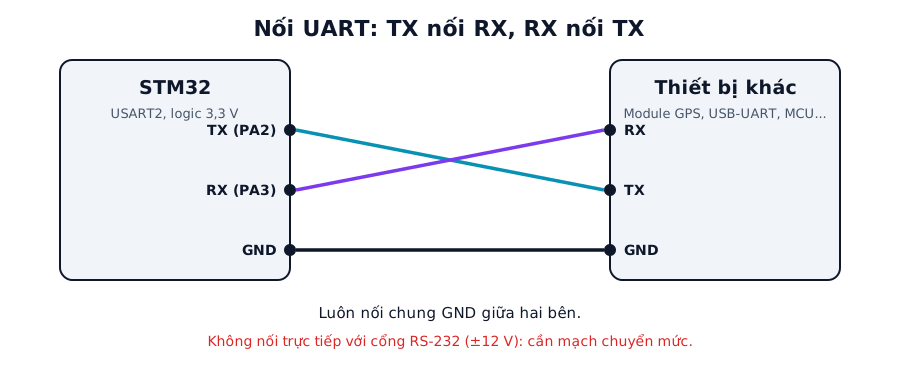
Figure 2. Cross TX to RX and always share GND. PA2 and PA3 are the USART2 pins on many STM32F4 boards; check the pinout of your part.
TX on one side goes to RX on the other, and the other way round. Both sides must share ground: a missing GND wire is a common cause of random garbage characters.
The logic levels must also match. The STM32 runs at 3.3 V, so before connecting a 5 V device check whether the RX pin is five-volt tolerant (FT). The RS-232 port on an old PC swings around ±12 V and will damage the MCU pin if connected directly. Use a level shifter such as the MAX3232 or a USB-UART chip instead. For long cables in a noisy environment, move to RS-485 (part 6).
4. Three ways to receive
| Mode | HAL function | Use it for | Drawback |
|---|---|---|---|
| Polling | HAL_UART_Receive |
Logging, quick tests | Blocks the CPU, drops bytes at high speed |
| Interrupt | HAL_UART_Receive_IT |
Small amounts of data, known length | One interrupt per byte, CPU cost |
| DMA + IDLE | HAL_UARTEx_ReceiveToIdle_DMA |
Continuous data, any length | More configuration steps |
UART has no standard end-of-packet character. On STM32 the usual answer is the IDLE line interrupt: once data has arrived, if the RX line stays quiet for one character time, the peripheral raises IDLE. Combined with DMA, the whole packet lands in RAM and the CPU is called only once, at the end of the packet.
5. Configuration in STM32CubeIDE
- Open the
.iocfile, go to Connectivity and enable USART2 in Asynchronous mode. - Parameter Settings:
| Parameter | Value |
|---|---|
| Baud Rate | 115200 |
| Word Length | 8 Bits (including Parity) |
| Parity | None |
| Stop Bits | 1 |
| Over Sampling | 16 Samples |
- DMA Settings tab: click Add and choose
USART2_RX. Set Mode = Circular, Data Width = Byte and enable Memory Increment Address. - NVIC Settings tab: enable
USART2 global interrupt(the IDLE interrupt needs it) and the interrupt for the DMA channel. - Clock Configuration: check the clock feeding the USART and the HSE source.
- Generate Code.
6. Source code
6.1 Polling: a simple echo
This is only for confirming that wiring and baud rate are right before doing anything else:
uint8_t c;
while (1) {
    if (HAL_UART_Receive(&huart2, &c, 1, HAL_MAX_DELAY) == HAL_OK)
        HAL_UART_Transmit(&huart2, &c, 1, 10);
}
6.2 Interrupt: one byte at a time
static uint8_t rx_byte;

void uart_start(void) { HAL_UART_Receive_IT(&huart2, &rx_byte, 1); }

void HAL_UART_RxCpltCallback(UART_HandleTypeDef *huart)
{
    if (huart == &huart2) {
        ring_put(rx_byte);                          // store the byte in the buffer
        HAL_UART_Receive_IT(&huart2, &rx_byte, 1);  // receive the next byte
    }
}
This is fine at low speeds. At 921,600 baud an interrupt arrives roughly every 10.9 µs, and the CPU spends a noticeable share of its time just copying bytes.
6.3 DMA + IDLE: packets of any length
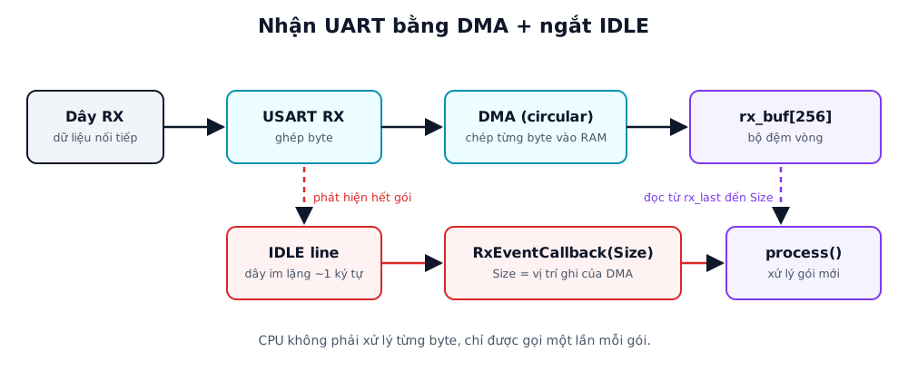
Figure 3. Data flow: DMA copies each byte into RAM without the CPU. When the RX line goes quiet, the IDLE interrupt calls the callback once to handle the new data.
#define RX_BUF_SIZE 256

static uint8_t           rx_buf[RX_BUF_SIZE];
static volatile uint16_t rx_last = 0;       // position processed so far

void uart_start_rx(void)
{
    rx_last = 0;
    HAL_UARTEx_ReceiveToIdle_DMA(&huart2, rx_buf, RX_BUF_SIZE);
    __HAL_DMA_DISABLE_IT(huart2.hdmarx, DMA_IT_HT);   // disable the half-transfer interrupt, keep only IDLE and full
}

// HAL calls this on an IDLE event or when the buffer is full.
// Size is the current DMA WRITE position in the ring buffer, not the number of bytes this time.
void HAL_UARTEx_RxEventCallback(UART_HandleTypeDef *huart, uint16_t Size)
{
    if (huart != &huart2) return;

    if (Size > rx_last) {                    // no wrap-around
        process(&rx_buf[rx_last], Size - rx_last);
    } else if (Size < rx_last) {             // DMA has wrapped around
        process(&rx_buf[rx_last], RX_BUF_SIZE - rx_last);
        if (Size) process(&rx_buf[0], Size);
    }
    rx_last = (Size == RX_BUF_SIZE) ? 0 : Size;
}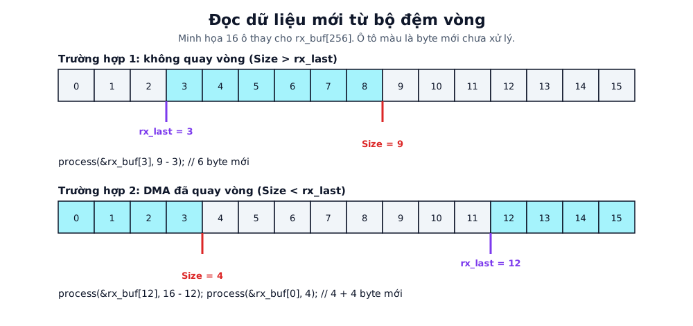
Figure 4. New data lies between rx_last and Size. If the DMA has wrapped to the start of the buffer (Size smaller than rx_last), read two pieces: from rx_last to the end, then from the start up to Size.
With circular DMA, do not call HAL_UARTEx_ReceiveToIdle_DMA again inside the callback. Doing so resets the DMA to the start of the buffer and the position arithmetic above breaks immediately.
The callback runs in interrupt context, so process() should only copy the data or push it to a queue and leave the heavy work to the main loop. If you need to tell half-transfer, full and IDLE events apart, use HAL_UARTEx_GetRxEventType(huart) and keep the half-transfer interrupt enabled.
Packets longer than the buffer are still handled correctly: the callback fires several times as Size grows and then wraps. After an error such as an overrun, HAL may stop receiving, so call uart_start_rx() again from HAL_UART_ErrorCallback. This behaviour differs between HAL versions, so check it against the one you use.
6.4 Transmitting with DMA
static volatile uint8_t tx_busy = 0;

int uart_send(const uint8_t *p, uint16_t n)
{
    if (tx_busy) return -1;                          // previous transfer not finished yet
    tx_busy = 1;
    if (HAL_UART_Transmit_DMA(&huart2, (uint8_t *)p, n) != HAL_OK) { tx_busy = 0; return -1; }
    return 0;
}

void HAL_UART_TxCpltCallback(UART_HandleTypeDef *huart)
{
    if (huart == &huart2) tx_busy = 0;
}
The buffer p must stay untouched until the DMA transfer finishes. Never pass a pointer to a local variable on the stack.
7. Common faults
| Symptom | Usual cause | Fix |
|---|---|---|
| Garbage characters | Wrong baud rate or format (parity, stop bits), inaccurate clock, no common GND | Check both sides' settings, use HSE, decode the line with a logic analyzer |
| Lost bytes, Overrun flag (ORE) | CPU cannot keep up in polling or interrupt mode | Switch to DMA, raise the UART interrupt priority |
| Constant framing errors (FE) | Floating RX pin, mismatched voltage levels, baud rate mismatch | Fix the wiring, check logic levels and baud rate error |
| Only part of a packet arrives, then nothing | DMA not circular, buffer smaller than the packet, receive restarted in the callback | Set Circular, increase RX_BUF_SIZE, do not restart in the callback |
Program hangs in HAL_UART_Transmit |
Huge timeout (HAL_MAX_DELAY) with no receiver attached |
Use a finite timeout or transmit with DMA |
| Transmitted data is corrupted | Pointer to a local variable passed to DMA, buffer overwritten | Use a static or global buffer |
8. Measurement plan
These measurements will replace the calculated numbers with real ones. The "Measured" column stays empty until the code runs on hardware.
| Test | Method | Calculated | Measured |
|---|---|---|---|
| Bit width at 115200 | Logic analyzer, measure the start bit | 8.68 µs | (to be filled) |
| Baud rate error at 921600 with HSE and HSI | Logic analyzer, measure bit width | +0.16% (HSE, fck 84 MHz) | (to be filled) |
| Maximum throughput at 921600 | Send 1 MB continuously, time it | 92,160 bytes/s | (to be filled) |
| Byte loss: polling, interrupt, DMA | Send 1 million sequence-numbered bytes, check at the receiver | No loss with DMA | (to be filled) |
| CPU load: interrupt vs DMA | Toggle a GPIO in the callback, measure duty cycle on a scope | n/a | (to be filled) |
| Delay from last byte to IDLE callback | Logic analyzer: compare RX with a GPIO set in the callback | About one character time | (to be filled) |
9. FAQ
What is the difference between UART and USART? A USART adds a synchronous mode with a separate clock pin. In the usual asynchronous mode they behave the same, and the USARTx peripherals on STM32 support both.
Why do I only get about 11 KB/s at 115200 baud? Each byte costs 10 bits on the wire (1 start, 8 data, 1 stop). 115200 divided by 10 is 11,520 bytes/s.
Should I enable parity? Parity only detects single-bit errors and cannot correct them. On a short, clean link use 8N1 and check integrity at the protocol level with a checksum or CRC, as Modbus RTU does in part 7.
How big should the DMA buffer be? Big enough to hold everything that can arrive between two callbacks being serviced, plus a margin. If the largest packet is 128 bytes, use 256 bytes or more. A buffer that is too small lets the DMA overwrite data you have not read yet.
What about an RTOS? In the callback, push a (pointer, length) pair to a queue or give a semaphore, and let a task do the processing. Never call a blocking function in the callback.
Summary
Before picking a speed, work out the baud rate error with the chip's real clock. Use HSE when reliability matters. For continuous data use circular DMA plus the IDLE interrupt, and remember that Size is a write position, not a byte count.
Part 2 moves on to SPI: a synchronous protocol, much faster than UART, with four CPOL/CPHA modes that have to match the device.
To compute a CRC or decode received bytes, try the Capitlab CRC calculator and Hex Converter.
References
- STM32 UART Idle Line Detection: Interrupt & DMA Reception (ControllersTech)
- The reference manual and STM32 HAL documentation for your part (USART, BRR and
HAL_UARTEx_ReceiveToIdle_DMA)